
No.27
Hi-Fi Audio
6N1P & SV83
![]()
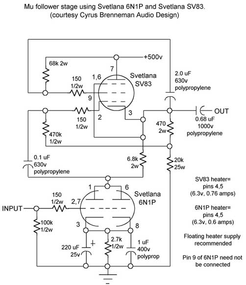
A High-Performance Mu Stage Using the
Svetlana 6N1P and SV83
By: Cyrus Brenneman
 Numerous
mu-follower and SRPP designs have been presented to the readers of audiophile
magazines in recent years. And yet, in spite of the limitations on present-day
receiving tube manufacturing, a large proportion of these designs have
used tube types which are no longer in production. Such designs are not
useful to the OEM of audio equipment, as he cannot be guaranteed of future
supplies of the tubes for his product line.
Numerous
mu-follower and SRPP designs have been presented to the readers of audiophile
magazines in recent years. And yet, in spite of the limitations on present-day
receiving tube manufacturing, a large proportion of these designs have
used tube types which are no longer in production. Such designs are not
useful to the OEM of audio equipment, as he cannot be guaranteed of future
supplies of the tubes for his product line.
The mu-follower presented here uses only Russian-made tubes of current manufacture. Its performance and sound are the equal of nearly any other mu-follower yet presented to the public or used in a commercial design. Thanks to the high transconductance and high linearity of the SV83 and the very high linearity of the 6N1P, distortion is vanishingly low at line levels, making this circuit excellent for no-feedback preamp line stages. And the large cathodes of the 6N1P offer superior performance and lifetime to 6922-type dual triodes.
This circuit, when operated on the full 500-volt plate supply shown, can drive a single SV572-3 effectively. If the SV572-3 is operated on its maximum 1000-volt supply, the resulting power output is in excess of 25 watts in Class A2. Other power tubes, such as the 300B, 211 or 845, are also suitable for use in SE designs using this mu-follower as a driver. In any case, it is recommended that the resistors and capacitors in this circuit be audiophile grade. Coupling capacitors should be polypropylene or PTFE dielectric. The 100k input resistor may be replaced with a 100k volume control if desired. The heaters of the SV83 and 6N1P may be operated on AC or DC, the latter being recommended for best noise performance in a line stage. Because the cathode of the SV83 is about 250v dc above ground, two methods of powering the heaters are recommended. One way would be to use separate supplies, one at ground potential for the 6N1P. The SV83 supply may then be stood above ground with a resistive divider attached to the 500v plate supply and then to either end of the heater, or to a center-tap in the filament winding of the power transformer. A simpler and well-tested method would be to use a single supply to power both the 6N1P and the SV83, floating completely free from the rest of the circuit except for a capacitor to suppress induced noise. This capacitor may have to be selected experimentally in a breadboard, for best noise suppression. Start with 0.22 uF, 600v, polyester dielectric. For best lifetime of the tubes in this circuit, a delay in the plate supply is recommended. A standby switch or a slow-warmup rectifier tube (such as the Svetlana 6D22S) are suitable methods of obtaining this delay. An electronic delay relay may also serve this purpose, with the delay set for at least 15 seconds to allow proper warmup of the 6N1P and SV83.
OBSERVED PERFORMANCE (measured on breadboarded prototype)
---------------------------------
Voltage gain at 1000 Hz:
about 30
Frequency response:
<10 Hz to >50 kHz, -1 dB
Maximum output signal into 47k-ohm load, at 1000 Hz, onset of clipping:
125v RMS (354 v p-p).
Distortion into 47k-ohm load at 1000 Hz:
0.08% at 10 v RMS out
0.45% at 100v RMS out