
No.22
Hi-Fi Audio
SV572-3
![]()
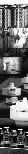
A Push-Pull SV572-3 Amplifier
By: Eric Barbour
 In
spite of the popularity of SE, the majority of high-end tube
amplifiers are push-pull in nature. There continue to be advantages
to push-pull, and industry sales are still dominated by push-pull-based
products. Furthermore, push-pull is the major standard for
guitar and music amplification.
In
spite of the popularity of SE, the majority of high-end tube
amplifiers are push-pull in nature. There continue to be advantages
to push-pull, and industry sales are still dominated by push-pull-based
products. Furthermore, push-pull is the major standard for
guitar and music amplification.
Presented here is a power amplifier using a push-pull pair of SV572-3s in Class AB1. The design is centered around the use of commonly-available components which are reasonably priced. All the components are available from Antique Electronic Supply (AES), except the chassis, M1 and some capacitors (Mouser) and the DC power supply for filaments (Lambda).
To date, very few amplifiers have been designed which feature variable loop feedback. My experiments with this circuit revealed that it could be made stable with the Hammond transformer and with a potentiometer to vary the loop feedback. The control shown allows continuous adjustment of feedback from nearly 0 dB to about 14 dB. Thus, the user has an opportunity to experiment with different settings, so that optimum speaker damping factors and distortion levels can be found for a given setup. Considerable work was undertaken on the bench to optimize this amp into a variety of resistive and reactive loads, regardless of the feedback setting. As the driver stage has been kept as simple as possible with available tubes, voltage gain of the amp is relatively low, especially with feedback at maximum. So, the amp is recommended for use with a preamp which is capable of 5 volts r.m.s. output.
Theory of Operation
Primary design goals were decided with an eye to both the high-end audio area and to musical-instrument amplification. Simplicity was regarded as desirable, to maximize reliability. Only current Svetlana tubes were used, so that availability of NOS tubes in the future would not be an issue. Operation of all components is very conservative, again for maximum reliability in professional-audio use. Although the driver stage was kept simple, this amplifier is not really intended for the beginning DIY builder - some experience is recommended.
The design, seen in Figure 1, is a straightforward driver and output stage. V1A is a high-mu triode which provides voltage gain of about 40. It is RC-coupled to V2A, which is connected as a split-load phase inverter. Potentiometer VR5 is used to adjust the AC signal balance of this phase inverter, to minimize output distortion. V2A is operated from a split supply of +150v and -150v, to prevent heater-cathode insulation damage.
V1B and V2B are used as gain stages with a voltage gain of about 8. These 7-watt pentodes are connected as triodes, with a conservative plate loading of 5000 ohms and a conservative plate-current operating point of 20 milliamps each. The screen resistors R9 and R12 serve to limit the current into the screen grids of V1B and V2B, thus preventing damage. The plate supply for these stages is about +500 volts, which allows a maximum voltage swing into each SV572-3 grid of about 400 volts at clipping. This is more than adequate for maximum power in Class AB1 operation of the power triodes. +500 volts is derived from the +650v supply through R25. Biasing of the output tubes is accomplished with potentiometers VR2 and VR3, using the same -150v supply used on V2A to provide an adjustable -72 to -150v grid voltage for the SV572-3s.
The SV572-3s are connected in the common manner, with their filaments operated from a single switching power supply. Since 6.3 volt supplies are unusual, we have found some Lambda supplies that produce +6.0 volts, a good compromise. The model EWS-15-6 is a special-order item designed for 6 volts, while the LZS-150-1 and SE-150-1 are 5-volt devices, available from Lambda stock, which can be adjusted up to +6.0 volts. All of these supplies are conservatively rated for this load, which is about 9.5 amps steady-state and much more at power-on. (Remember, tube filaments draw much more current when cold than at operating temperature--switching supplies are usually limited in their transient current capability, and must be derated when used to run tube filaments.) All switching supplies can produce RFI at frequencies greater than 20 kHz, so regardless of the supply used, C113 may be required and is recommended. It should be mounted directly to the SV572 socket tabs - be sure to get the polarity right.
The output transformer shown is a Hammond 1650R, which has a primary impedance of 5000 ohms plate-to-plate. As the SV572-3s will give best performance on a higher load impedance, the 1650R is connected so that it appears to have a 10k-ohm primary. This is done by simply connecting the 8-ohm load to the 4-ohm output tap. Although this can degrade frequency response, the effect is minimal in this circuit, and hi-fi performance is still possible. For musical-instrument use, the Hammond transformer gives excellent performance, especially compared to more conventional tube amplifiers which are often used for live music amplification. There are now some push-pull output transformers available with higher primary impedances, which are much more expensive than the Hammond and will give somewhat better performance. Ultimately, the choice of output transformer is up to the constructor and his budget.
Capacitors C2, C11 and C12, and resistor R21 serve to stabilize the amplifier at all feedback settings. Their values are not critical. An assortment of reactive loads and speakers have been attached to the prototype, and no instability or oscillation were observed with the values shown. C2 and C12 serve to limit high-frequency response and correct phase shift, while C11/R21 are a load network, which provides some capacitance on the output regardless of the speaker load. Even though great pains were taken to insure stability, some speaker loads may not work properly on this amplifier. It is difficult to build an adjustable-feedback amp of this type and be certain that it is well-behaved under all conditions. It's advisable to test it on the bench with the desired speaker load on it, with an oscilloscope attached in parallel, to allow watching for spurious oscillation.
The power supply (Figure 2) uses readily-available components throughout. The rectifiers are Svetlana 6D22S types, which are of the TV horizontal damper-diode type. Their slow warmup and very conservative operation will help minimize the chance of failure, as the SV572-3s warm up far more quickly than the 6D22Ss. This diode is unusual in that it has a cathode cap rather than a plate cap. A connector for the cap with an insulating boot is recommended. The Svetlana PC509 has a ceramic body which completely covers the cap; nevertheless, if safety is an issue here, a cage over the tubes or an enclosed chassis is recommended.
A small 120v-120v isolation transformer and voltage doubler rectifier are used to produce +150v for the driver and -150v for the phase inverter and bias network. PS101, discussed above, may be one of the Lambda models shown or a surplus unit capable of being adjusted to produce +6vdc under load. If a single choke capable of 200 mA DC continuous operation is available, it may be used in place of L1 and L2 - we used a pair of 150-mA chokes here for conservatism.
If the amplifier will be used in a professional setting, the input jack should be a 1/4" panel-mount type. Alternatively, both RCA and 1/4" jacks can be provided on the input, and both binding posts and a 1/4" jack may be provided for the speaker output.
Adjustment
Upon completion of the amplifier, install all the tubes and set the bias controls VR2 and VR3 to give the most-negative voltages to the SV572-3 grids. Power it up (no standby switch is needed), and observe the plate current meter. If it exceeds 250 mA, power off and examine the circuit for errors or for faulty components. Then set VR5 to its midpoint, and turn VR4 and VR1 down fully.
Once the amplifier has been verified to idle properly, bias adjustment may be performed. Shut off power and remove both SV572-3s. Power up again and observe the current drawn by the 6BM8s alone, which should be about 45 mA. Power down, install V3 in its socket, and power up again. Adjust VR2 until the plate current meter shows 105 ma (60 mA for the triode plus 45 mA for the 6BM8s). Power down, install V4, power up again, and adjust the current meter to read 165 mA. Due to the difficulty of attaching cathode current meters to directly-heated triodes in a circuit such as this, it is necessary to adjust each triode's bias separately and add that current to the rest of the circuit. This scheme works quite well, and even with an old surplus 250 mA meter for M1, gives repeatable current balance in the output transformer to within 5 mA. More accurate adjustment is not required by the transformer; we have tried considerably greater DC unbalances with only a small effect on distortion and low-frequency response.
If desired, the AC balance of the phase inverter can be adjusted in two possible ways. The least expensive way involves mixing the phase-inverted outputs together and adjusting VR5 for minimum fundamental, as follows: a) remove power, pull V3 and V4 out of their sockets, and open the case. Attach one end of a 1-megohm resistor to pin 3 of V1. Attach one end of another 1-megohm resistor to pin 3 of V2. Connect the free ends of these resistors together, and attach the probe of an oscilloscope to this point. (Alternatively, the 1-meg resistors could be soldered to small screws or pins, which are then inserted into pin 3 on the V3 and V4 sockets. Be careful not to let anything short to the case, and be VERY careful not to plug the resistors into pin 2 of the V3 and V4 sockets.) b) attach a sine-wave generator to the input jack. Frequency setting is not important, 1 kHz is commonly used. Set the scope's sweep rate to 500 usec/division, and set the vertical sensitivity to 1 volt/division. c) carefully power up the amplifier. Set the volume control VR1 and the signal generator's level control until you observe the signal on the scope. It should appear like two dissimilar sine waves mixed together; one is the 1 kHz fundamental, the other is the 2 kHz second harmonic. d) then adjust VR5 until the fundamental is nulled out; you will find a point where VR5 can be rocked back and forth, and the fundamental will disappear, leaving only the second harmonic. Leave VR5 at that null point, remove power, and reassemble the amp.
PERFORMANCE RATINGS
(using Hammond 1650R output transformer)
Power output into 8 ohms: 35 watts (16.7 volts RMS) at 5%
distortion
Input for full power, volume control at maximum:
- with feedback minimum: 1 volt RMS
- with feedback maximum: 5 volts RMS
Frequency response, -3 dB, at 20 watts out:
- with feedback at minimum: 27 Hz to 15.7 kHz
- with feedback at maximum: 22 Hz to 40 kHz
Hum and noise, within audio band:
- with feedback at minimum: 3.9 mV p-p
- with feedback at maximum: 2.7 mV p-p
AC power consumption, at 35 watts into 8 ohms:
220 watts at 120 vAC.
PARTS LIST
AMPLIFIER
Resistors: all are 1/2 watt carbon film or metal film unless otherwise specified.
R1 |
120k ohm, 2 watt |
Variable resistors:
VR1 |
100k ohm audio taper |
Capacitors: all are 630v film types except as noted.
C1, C3, C4, C11 |
0.22 uF |
Transformers:
T1 |
output, 5000-ohm plate-to-plate |
Tubes:
V1, V2 |
Svetlana 6BM8 |
Misc:
2 x 9-pin miniature sockets
|
POWER SUPPLY
Resistors:
R102-R105 |
150k ohm, 2 watt |
Capacitors: all are 450-volt electrolytic axial unless otherwise specified.
C101-C108 |
100 uF |
Diodes:
D101, D102 |
1N4007 or similar |
Tubes:
V101, V102 |
Svetlana 6D22S |
Transformers and chokes:
T101 |
400-0-400v 200 mA plus filament |
Misc:
2 x magnoval sockets for V101/102
|