
No.28
Hi-Fi Audio
SV572
![]()
SV572 Test Report: Modernized 211 - New
DH Audio Power Triode
By: Hisashi Ohtsuka

A new tube type which challenges amplifier designers has been introduced by Svetlana Electron Devices, Inc., the SV572 Series Triodes. With its small outline dimensions, it is similar to a downsized 211, yet withstands a 125 watt plate dissipation. There are four amplification factor versions offered, and therefore applicable from audio to industrial use. Although manufactured in Russia, total activity, from planning through sales, of the vacuum tubes are handled in the U.S. under Svetlana Electron Devices, Inc. Detailed information and reference on the characteristics and application of these triodes is available. We feel that this should be normal for precision industrial products like vacuum tubes, but in reality, this is not always seen with the products of Eastern European or Chinese tube makers. As to the availability of the SV572 Series, it seems that only a limited supply is available at few stores here in Japan, although this situation may improve as the popularity increases. The expected sale price in Japan may be on the order of ¥12000 to ¥13000 for each tube.
There have been a few interesting triode power tubes appearing recently. We are placing the new SV572 Series in such a group.
It was last September when we first saw this type of tube at Svetlana Electron Devices office near San Francisco during our visit (refer to page 29 of January, '97 of MJ). And then tests were conducted on the samples shipped by Svetlana shortly afterward.
Svetlana seems quite good at modifying existing transmitting tubes to suit audio application as seen in an example of the SV811 Series. However, we are unable to find 572 as a valid type in our references at this time so we will treat this as a new type of tube.
The SV572 Series has four versions of the µ (amplification factor) values: 3.5, 9.5, 29.5 and 160. The specimens we are reporting on at this time are one pair of the SV572-3 (µ3.5) and one pair of the SV572-10 (µ9.5). Their published rating are shown in Table 1.
Emission Characteristics
The measurements were made in the same manner as in pages 129-134 of
August, '96 and pages 104-107 of July '97 issues of MJ Magazine.
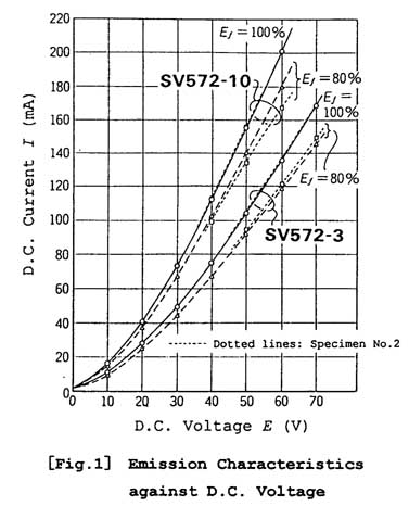
Figure 1 indicates the tested relationship between applied voltage (E) and current (I) which flows into the diode-connected specimen. Seperate lines indicate the published curves, specimen No. 1, and specimen No.2 of each tube type. It is obvious that SV572-10 shows higher current (perveance) level than SV572-3. But both types demonstrate that differences between the current values at 100% of Ef (filament voltage) and the current at 80% of Ef are quite small, and also these curves are not off the theoretical curve: I=G . E 3/2 (G: perveance factor). Therefore these tubes can be rated as having very good characteristics.
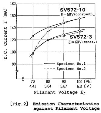
Figure 2 shows the drop in I when lowering Ef from its 100% (6.3V) with E unchanged. It was necessary to select E as 60V on SV572-3 and 50V on SV572-10 to obtain value of I around 150mA when Ef =100%.
The curves suggest that these specimens are in good condition as the drop in emission current when Ef is lowered to its 80% is small. Only specimen No.2 of SV572-10 indicates a little steeper drop, but this should not be rated insufficient judging from our past experience.
The filament material selected in SV572 Series is the thoriated tungsten. For evaluation, we should consider the difference between the oxide-coated filament types like the 300B and the thoriated tungsten types. First, the absolute value of emission current of the oxide-coated type against the same filament heating power is much higher than that of the thoriated tungsten type. Therefore, more margin for the necessary current can be secured. On the other hand, it takes more time to stabilize the current in an oxide-coated filament when the operating temperature changes. This happens because it relies on a complex electron-emitting mechanism.
Taking an actual example of the specimen No.2 of SV572-10, I at Ef =70% drops down to 61% of its initial value, but it stays on that point. If this is the case of typical oxide-coated type, the current I should drop down gradually by the time as its temperature lowers, and in extreme cases, keeps dropping down almost to zero.
The reason for this phenomenon, in our opinion, must be due to the simplicity of the throiated tungsten type as its amount of emission should be determined solely by the treated material and the operating temperature.
Static Characteristics
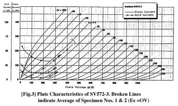
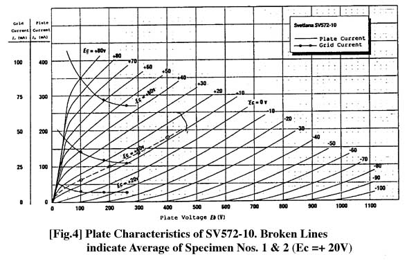
Figures 3 and 4 show the published plate characteristic curves by Svetlana
with the measured points marked on. All specimens show similar tendencies
(ie. a little slow in 'build up' areas at Ec=0V on SV572-3, and +20V on
SV572-10), and also a little shallower grid bias required for keeping the
specified plate current on the designated operating points as noted in
Table 2. However, this should not be a big matter to discuss here as these
curves supplied by the manufacturer should only be treated as typical examples.
Appearance and Structural Features
The glass envelope employed is a heat-resistant type of a variant of T-14
(45.5mm in diameter, 133mm in height excluding pins), and therefore looks
quite slim. The plate dissipation of 125 watts is 25% more than 211 and
845 types, but the tube is actually a bit smaller in size than the old
brothers. The base is ceramic UX type.
The internal construction is like a typical transmitting tube of high voltage, high-temperature operation. The plate is titanium-coated solid graphite, and the grid wire seems to be designed by changing its pitch to obtain desired µ values. The filament is made of M-shaped thoriated tungsten wire, and tension is applied at the top with coil springs. The operating temperature of the filament seems relatively low for a thoriated tungsten type. The assembled electrode is supported by ceramic spacers at both top and bottom, and mica is only used for fixing the electrode structure against the glass envelope with the aid of spring bars. There is no getter visible, which means the plate must have excellent gas absorbing capability.
Conclusion
According to Svetlana, the SV572 Series, introduced after the SV811 Series,
uses a special tungsten wire with high ductility, applies throium doping
and other processes to obtain good performance. This type is particularly
suited for the larger-size and high-voltage tubes as it is tougher against
ion attack than oxide-coated types, and also lesser in shot noise. Although
it has its limitations in emission efficiency and peak current supply capability
compared with the oxide-coated type, this type is well suited for audio
application, and has very good sound.
Examining the initial portion of the plate characteristic curves of SV572-3, plate current Ib at Ec=0V and Eb=100V is only around 35mA (with Svetlana curve), and it is below 30% of the same conditions in 300B (approx. 130mA). Therefore this type of tube should be more suited for high plate voltage operation. In such a case the lower-µ type requires extremely high grid swing. Looking at an example of operating conditions in Table 2 (class-A2 single), the output power of the type with 3.5 µ seems relatively small compared with its very high drive-voltage required. Instead, we look at the way that the optimum point may lie at a higher µ range, and the type with 9.5 µ may be more suited for the single-ended audio output stage with a moderate power drive. Also, we feel that it would be interesting if there were another type that existed in between 3.5 and 9.5 µ value to determine the optimum point.
It is almost unbelievable to see 125 watts of plate dissipation from its physical size, but this is true. During our evaluation tests the plate of the SV572-3 turned slightly red at 112.5 watts of dissipation. But according to Svetlana, there should be no problem to use it continuously with its plate red, and the characteristics may even improve (by absorbing more gas and an improved degree of vacuum, we assume).
General appearance of the SV572 Series is quite impressive, and enough to let us believe that the quality control must be excellent as there are only little variations noted among the specimens in the tested parameters although the specimens offered this time are matched pairs.
Anyway, we welcome the birth of such charming power triodes.
Figure 1
Figure 2
Figure 3
Figure 4
| Table 1 (Published Ratings by Svetlana) | SV572-3 | SV572-10 | |
| Key Ratings
Filament: Voltage (AC or DC) (V) Current (A) Amplification factor (nominal) Tranconductance (nominal) (Gm: µS) Plate resistance (nominal) (rp: *) Maximum ratings DC plate voltage (Eb: V) Maximum-signal DC plate current (Ib: mA) Plate Dissipation (W) Grid Current (Ic:mA) Typical Operation, Class A2, Single Plate voltage (V) Grid voltage (V) DC Plate current, zero signal (mA) DC Plate current, max signal (mA) Effective load impedance Power output at 5% distortion (W) Typical Operation, Class AB2, Push-Pull (for two tubes) Plate voltage (V) Grid voltage (V) DC Plate current, zero signal (mA) DC Plate current, max signal (mA) Effective load impedance (plate to plate) (*) Power output at 5% distortion (W) |
-
- - - 3.5 1800 1900 - - - - - - 750 -120 140 170 5000 25 - 1000 -210 200 310 800 75 |
-
Thoriated-tungsten 6.3 ± 0.3 4 - - - - 1000 210 125 50 - - - - - - - - - - - - - - |
-
- - - 9.5 4500 2100 - - - - - - 750 -35 140 190 5000 40 - 1000 -65 200 340 8000 150 |
| Table 2 (Measured Values of Each Specimen) | |||||
| Tube Type | SV572-3 | SV572-3 | SV572-10 | SV572-10 | |
| Specimen No.
Filament Current (A) Initial Portion of Plate Characteristics Ec (V) - Eb = 100V Eb =200V Eb = 300V Eb = 400V Operating Conditions Eb (V) Ib (mA) Ec (V)*1 Gm (µS) Ic (µA) *2 *1: From Svetlana Curves, Ec values can be read as -91/-120V for SV572-3,
and -27/-37V for 572-10 |
1
- 3.85 - 0 - 29.3 77.4 136.7 206.0 - 600/750 120/150 -85.7/-113.3 2100/2180 +1/+5 |
2
- 3.86 - 0 - 29.0 77.4 138.5 210.0 - 600/750 120/150 -87.5/-114.7 2100/2180 +3/+ |
-
- - - - Ib (mA) |
1
- 3.92 - +20 - 62.6 97.5 135.5 176.2 - 600/750 100/120 -19.9/-29.2 3430/3550 +1/+2 |
2
- 3.82 - +20 - 64.5 101.1 140.3 182.9 - 600/750 100/120 -21.1/-31.3 3400/3650 +1/+1 |
**The information provided in this application note is intended for general design guidance only. The user assumes all responsibility for correct and safe usage of this information. Svetlana Electron Devices does not guarantee the usefulness or marketability of products based on this material.