
No.42
Amateur Radio
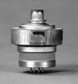
4CX800A
![]()
A 144MHz Amplifier Using the Svetlana 4CX800A
By: Alfred Green, NU81

 Article as first presented
at the WSWSS 3rd Annual Conference - October 1997
Article as first presented
at the WSWSS 3rd Annual Conference - October 1997
This article describes the design and construction of a high power, 2-meter amplifier based on the low-cost 4CX800A tetrode. The unit provides a substantial power advantage over the standard 'brick' type amplifiers, whilst giving good intermodulation performance with a low drive requirement.
Introduction
For serious weak-signal operation the typical 150W 'brick' type amplifier is barely adequate. For particularly demanding modes, such as meteor-scatter and moonbounce, power levels approaching the legal limit are desirable. Although there are a few solid-state amplifiers in the 400W range, they are expensive and tend to be fairly 'broad'. This is due mainly to trying to squeeze a large amount of power out of devices running at low supply voltages, and the resulting problems associated with distributing large amounts of current. Higher voltage devices, such as the Motorola MRF151G power MOSFET, can provide better performance, but the cost is still prohibitive for most amateurs, particularly when it is considered that several devices must be used to reach the 1kW level.
To approach the legal limit at 144MHz, tubes are the only practical choice. The most popular device is probably the 8877/3CX1500 running in grounded grid configuration. In many cases, however, particularly for terrestrial use, a power level of 800W - 1kW is practically equivalent, while offering more choices for the devices and circuit configurations. There have been many designs using the 4CX250 series of tubes, usually employing two tubes in a push-pull arrangement. Although this circuit can give 1kW output on CW when operated in class-C, for SSB use it is not really suitable for much over 500W if linearity is to be maintained. Other tubes in the series, such as the 8930 or 4CX350 can provide somewhat more output, but there is still the complication of having to carefully match a pair of tubes to get the desired performance.
A single tube solution is definitely more straightforward to implement, and a popular design has used the 3CX800 grounded-grid triode. For the intended application, however, it had two disadvantages:
1.) The required drive level of about 20W was more than that available from most of the common transceivers, which are limited to the 10W range. An example is the popular IC706.
2.) Being grounded grid, the negative side of the high voltage supply needed to be isolated from the system ground. This makes it difficult to arrange for multiple amplifiers to share a common supply.
For those reasons, it was decided to use a grid-driven tetrode circuit. To obtain the desired 800W+ from a single tube, the logical choice was the recently available Svetlana 4CX800A. It includes the following specifications:
800W Plate dissipation, forced air cooled
2.5kV maximum plate voltage
150MHz frequency for full ratings
12.6V, 3.6A heater
and typical operation, (given for 60MHz),
Power output 780 W
Plate voltage 2.2kV
Screen voltage 350V
Zero-signal plate current 360mA
Max signal plate current 630mA
Screen current 30mA
Peak RF grid voltage 35V
Plate dissipation 600W
At a new cost of under $200, this represents a good fit for the chosen amplifier parameters.
Circuit Summary
The amplifier is designed to be used in conjunction with an external power supply that provides approximately 2200V for the plate, and 400V to supply the screen regulator. The high voltage supply includes metering circuitry for voltage and current, and other important features such as inrush current suppression and flashover protection. The screen regulator, the 12.6V heater supply and the adjustable negative control grid bias supply are included as part of the amplifier, and will be described in the following sections.
Within the amplifier itself, there are two major sections: RF circuitry, and power control and interlocks. The function of the RF section is to provide the necessary impedance matching and filtering to enable the tube to provide the desired power amplification within a nominal 50ohm environment. To do this, precise voltages are needed for optimal performance, along with provision for handling abnormal situations.
RF Circuits-input
The 4CX800 may be run with a passive grid circuit, nominally 50ohms. This is to ensure stability, without requiring neutralization. However, to obtain a peak RF voltage of 35V across a 50ohm resistor, a driving power of 12.3w would be needed. For a maximum input of 10w, the resistance would need to be 61.3ohms. This is still low enough to swamp the grid, and the need for neutralisation is avoided.
To provide a good match to 50ohms, a pi-circuit is used. The output capacitance is formed from the input capacitance of the tube, nominally 51pF, along with a few pF of strays. An inductance of 38nH, and input capacitance of 60pF, completes the matching. When tuned for best response at 144.2, the input swr was better than 1.1 up to 145MHz, so no tuning adjustments needed to be provided.
The grid resistor is formed from a parallel combination of 5 x 560 ohm and 5 x 680 ohm resistors, giving a net value of 61.4ohms. As this resistance must dissipate essentially all the input power, each resistor was chosen to have a 2w rating, so that even under continuous key-down operation there is still a margin of safety. Whilst carbon composition resistors are preferable, they are becoming difficult to find, so common metal-film devices were used. With the resistors connected in parallel, the inductance was low enough not to be a factor.
The 60pF input capacitor, and 680pF isolation capacitor were chosen to be Unelco metal-clad mica types, although silver-mica ones would probably be satisfactory at this power level.
RF Circuits-output
The output tank circuit is a shortened, grounded quarter-wave line. The line is dimensioned to have an approximate characteristic impedance of 75ohms, which is about optimum for minimum circuit losses. The line is formed from two aluminum plates separated by a 10mil Teflon sheet. This forms the plate coupling capacitor, with a value of approximately 500pF. The upper side of the line is connected directly to the plate cooler using a hose clamp. The lower line is directly grounded through a set of four metal spacers. This provides a low inductance path to ground. The circuit is tuned to resonance by a 40mm diameter disk, with the spacing adjustable from the front panel. Various output arrangements were tried, including capacitive and link coupling, but the best results were obtained with a direct connection to the plate line. This has the disadvantage of not allowing adjustments to the loading when the amplifier is in use, but in practice this has not been necessary, as the unit is always operated into a good 50ohm antenna system. The connection is made to a plate in contact with the lower line, and which is provided with a slot so the connection point can be adjusted. A good starting point for this is 29mm from the line through the grounding pillars.
Power Supplies
The function of this part of the circuit is to provide the correct voltages for the tube, and also to handle the sequencing and interlocks to ensure tube safety. There are four major components to this: heater supply, grid bias supply, screen regulator and interlock circuit.
Heater Supply
It may seem like overkill to provide a stabilised supply for the heater, but there are at least two very good reasons for doing this. First, when power is initially applied the filament is cold and has a very low resistance, less than 1ohm. The resultant current surge stresses both the transformer and the tube. Incorporating a softer start for the heater will enhance the longevity of these components. Secondly, one of the primary goals for the amplifier was to provide some needed 'punch' to the portable contest station. For this, it needs to run for long periods off a generator, which tends to be only moderately regulated. Significant voltage swings would take the heater out of the specified operating range, and cause either inefficient operation or damage to the tube. In addition, an interlock is provided to prevent the heater supply from being established if there is insufficient back pressure in the plate cavity caused by a blower failure.
The center tap of the transformer is taken to ground through a KC004 NTC inrush current limiter. This reduces the surge which would otherwise result as the filter capacitor is charged. The rectifiers are chosen to have a low forward voltage, so that there is sufficient drop across the regulator transistor even when the incoming AC supply drops to its lowest expected value. The regulator uses a PNP transistor as the pass device, Q1, and a further PNP device, Q2, to amplify the output of the LM358/748 op-amp, IC1. The current source for the regulator is enabled by supplying a +5v signal to the gate of Q3. This signal is derived from the interlock circuit when the contact from the pressure switch is true. Without this, the regulator is essentially off, and no voltage is passed to the heater.
Current limiting is provided by the 0.1ohm resistor following the pass transistor and Q4 which shunts the top part of the voltage divider if the current to the heater exceeds approximately 7A. This has the effect of reducing the base drive to the regulator transistors, and thus clamps the heater voltage until the filament has warmed up sufficiently.
After the supply has settled above approximately 11V, the timer IC2 is started. This provides a nominal 3 minute delay before the amplifier can be operated. The output from the timer circuit is used to disable the screen supply. This ensures that at least the specified 2.5 minute warm-up period is achieved before the amplifier can be operated at full power.
Grid Supply
As this amplifier is intended to be run only in Class AB1, ie. no grid current, a simple voltage divider could have sufficed. However, with the varying supply voltage resulting from the previously mentioned portable environment, a stabilised supply is a definite advantage.
Initially, it was intended to provide a higher negative voltage to ensure that the tube was completely cut-off when not transmitting. It was found, however, that clamping the screen at 0v achieved the same result, so the control circuit was simplified to maintain a constant bias voltage. Consequently, it would be possible to use a lower voltage supply and reduce the dissipation of the ballast resistors, but this was not implemented.
To protect the circuit from voltage spikes resulting from flashovers in the tube, a VDR was included at the output of the supply, as well as one at the feedthrough capacitor connecting to the 61ohm grid terminating resistor.
The supply is derived from a 115/36vac transformer connected in reverse, and driven from the 28vac from the transformer feeding the heater supply. After rectifying and smoothing this, approximately -120Vdc is available. The regulator amplifier and the reference voltage is derived via a -20v zener followed by a low power -12v 3-terminal regulator. The output from the amplifier drives the base of the shunt regulator Q1. The variable resistor RV1 allows the output voltage to be set in the range of about -60v to -40v to adjust the zero signal standing current. Note that this component is mounted so it is adjustable from the top of the chassis, so that the standing current can be adjusted while the amplifier is operating.
Screen Supply
Tight regulation of the screen is important to ensure that the amplifier meets the low intermodulation requirements. It is also necessary to provide protection against voltage spikes and excessive screen current. The screen is grounded on receive, and the screen control relay is disabled by the screen regulator if any trip conditions are detected. Much work has been done on screen regulation, particularly in Europe, so rather than re-invent the wheel the circuit designed by G3SEK was used. *
Interlock Circuit
There are four conditions which are monitored;
blower pressure
grid bias
heater delay
plate voltage
The blower pressure is detected by a pressure switch in the plate compartment. It closes when the blower is operating. If the pressure is too low, the switch opens and Q1 turns on. This pulls down the screen enable line, and also turns off the heater supply.
The grid bias is detected by Q2 and the potential divider feeding its gate. If the bias falls below -40v, Q2 will turn on and disable the screen.
The output of the 3 minute delay circuit on the heater regulator board is tied directly to the disable line.
The presence of the high voltage plate supply is detected by Q3, driven from a potential divider formed as a chain of ten 100k, 1W resistors and a 10k resistor to ground. The 10k variable resistor across the gate is adjusted so that Q3 turns on if the plate supply is more than about 1kV. This is necessary to prevent excessive screen current from flowing if the plate supply fails. If there is insufficient voltage to enable Q3, then Q4 will be turned on and the screen enable line will be pulled low.
Each of the interlock lines has its own associated LED to indicate the source of the problem. There is a single LED driven by Q5 which lights when all conditions are satisfactory and the amplifier is ready to operate. (The Sby/ready input is optionally used with a safety-interlock chassis switch, and should be left unconnected if not used.)
Construction
The main structure of the amplifier is a BUD chassis, AC427, which has outside dimensions of 4x10x17 inches. This is bolted to a 8" high standard rack panel. The tube is mounted horizontally inside the chassis, with the cooler directed to the rear. The plate compartment is formed by a divider bent from 18ga aluminum, having dimensions of 12.5 by 4 inches by 3.95 inches high. A 1/2 inch lip is provided, and #6 captive nuts are pressed in place to secure the cover. These give better reliability than the more common self-tapping screws.
The grid compartment is also bent from 18ga sheet, with dimensions of 1.75 x 3.75 inches. The blower feeds into the plate compartment through a rectangular hole cut into the rear wall of the chassis. The air passes through the plate cooler, and is directed via a chimney made from 25mil Teflon sheet to the outside. The chimney support and outlet screen plate are made from hobby type 32 mil brass sheet. A 3" diameter hole is cut into the chassis so that this assembly may be removed, permitting access to the tube.
As was mentioned earlier, the plate line is constructed from two aluminum plates, each 200x40 mm. The upper plate is cut to provide a 10mm wide, 10mm high lip which is clamped to the tube cooler. A further piece, 50x55 mm, has a slot cut into it to provide an adjustment of the output loading connection. This piece is clamped between the lower part of the plate line and the shorting posts. A ceramic stand-off pillar is provided at the tube end of the line to act as a support, and the two plates, with the Teflon insulation between them are clamped together in five places with Nylon hardware.
The plate supply voltage is fed into the compartment via a high voltage feedthru and is connected to the upper plate.
The tuning disk is mounted on an 8/32 brass screw, which is grounded to the base of the plate compartment using a tapped spring loaded bushing fabricated from plumbing fittings. The screw is clamped into a 1/4" rod, which goes into a reduction drive. The rod is a sliding fit in the drive, and a groove is cut into it to hold it in position. This gives a very smooth tuning action.
Within the grid compartment, the cathode pins are connected together and to ground using a ring cut from 16 mil brass sheet. The heater pins are connected to feedthrough capacitors via ferrite loaded chokes. The screen connection has a transient absorber, Panasonic V10D431, connected directly to ground, and a choke to the feedthru mounted on the sidewall. The grid loading resistors are mounted on L-shaped brackets made from 16 mil brass sheet, with the resistors being arranged in two rows of five. One side is connected directly to the grid pin, and the other end is supported by two feedthrough capacitors. The input BNC connector is mounted to the side of the grid compartment, and a small piece of circuit board holds the coupling and matching capacitors. The matching inductor is supported between this board and the brass sheet connected to the grid pin.
On the rear panel are the 115v supply cable and associated fuse, a 1/4" threaded grounding post to connect to the high voltage supply, the RG213 cable to carrying the plate voltage, a 2-pin Molex connector for the 400v supply for the screen regulator, and a phono socket for the PTT line.
The RF connections are brought through to the top side of the chassis, where the input and output relays are mounted on a plate. A low-pass filter and power sensor are also mounted here.
Start-up
LETHAL VOLTAGES ARE PRESENT IN THIS AMPLIFIER. USE EXTREME CAUTION WHENEVER ANY OF THE CIRCUITS ARE EXPOSED!
Initially, do not connect the high voltage and the screen supply. Remove the tube, and link across the pressure switch. Turn on the power, and observe that the interlock LEDs for heater delay and HV are both on, and the Ready light is out. Measure the bias voltage at the grid pin, and adjust RV1 on the bias board to give a reading of around -40v. Adjust the bias trip setting RV1 on the interlock board until the threshold is found. Adjust the bias setting to maximum negative, which should be around -60v. Measure the heater voltage, and adjust with RV1 on the heater board for a value of 12.6v. Check that the heater delay times out after a minimum of 3 minutes. Connect the grounding strap between the rear stud and the high voltage power supply. Connect the high voltage cable to the supply and turn it on. After the supply has stabilised, adjust RV2 on the interlock board until the HV interlock LED just turns on. Measure the gate voltage at Q3, and adjust RV2 until the voltage is 25% above the threshold. Connect the 400v screen regulator supply, and follow the directions in the G3SEK document, with the current source setup for 50mA and an output voltage of 350v.
Turn off and disconnect the high voltage supplies. Using a shorting strap, eg. a short length of insulated wire with alligator clips, ground the plate line. Insert the tube, and place the chimney assembly over the cooler. Fasten in place.
Connect a low-power (~1w) source and a SWR bridge to the input BNC socket. If the input VSWR is more than 1.1:1, then remove the grid circuit cover and adjust the inductor by squeezing or expanding it.
Adjust the plate tuning capacitor to be approximately 3mm from the plate line. Connect the RF output to a power meter and dummy load and the input to a source capable of being adjusted from 1 - 10w. Removed the plate shorting link, and re-attach all the covers. Reconnect the high voltage supplies. Turn on the power to the amplifier and the HV supply, and wait until the Ready light is on. With no RF input, enable the PTT line and monitor the plate current. With the bias at -60v, as set earlier, the standing current should be less than 100mA. Gradually adjust the bias voltage for a setting of 360mA. The exhaust air temperature should feel noticeably warm, but not excessively so. Apply approximately 1W to the input, and observe that the plate and screen current meters show changes (the screen current may reduce or go negative, this is normal). Adjust the plate tuning capacitor for a peak in screen current. Slowly increase the input power, and observe that plate and screen currents, and RF output all increase smoothly. Occasionally adjust the tuning to peak the screen current. Continue until the screen current reaches 30mA, or the maximum 10w input is reached. If the screen current reaches its limit early, this is an indication that the output loading is too light. If the current is less than 25mA and the plate current is reading over 600mA, then the loading is too heavy. In either case, the amplifier needs to be shut down and made safe, and the tap on the output line adjusted. Moving the connection away from the ground point increases coupling, and vice versa.
When these adjustments have been completed, the amplifier should be operating correctly. It should be stressed that the tuning should always be done to maximise screen current; this will closely match the setting for maximum power output. Tuning for highest power will result in the tube being at an incorrect operating point, with an increase in the intermodulation.
Results
The amplifier has been very easy to setup, and is completely stable in operation. Although no quantitative measurements of intermodulation have been possible, on-air tests have shown the signal is very clean, comparable to the IC-706 being used as a driver.
The following results were obtained:
Plate voltage: 2180v
Plate current, zero sig: 360mA
Plate current, max sig: 645mA
Screen voltage: 350v
Screen current, max sig: 28mA
Grid bias voltage: -47v
Drive power: 9.5w
Output power: 820w
* A complete set of boards for 4CX800A VHF and HF amplifiers is available. These boards and components are the complete power supply, protection and control circuitry (less R.F. deck and H.V. supply) for tetrode amplifiers such as this. The kits are available for the 4CX400A, 4CX800A and 4CX1600B tetrodes.
Contact:
Mr. Ian White
G3SEK Tetrode Boards
52 Abingdon Road, Drayton
Abingdon, Oxfordshire OX14 4HP
ENGLAND
website: www.ifwtech.demon.co.uk/g3sek/tetboard/tetboard.htm
email: tetrode-boards@ifwtech.demon.co.uk
Physical Layout of 144-MHz Amplifier Schematic of RF section of 144-MHz Amplifier Construction of stripline for 144-MHz Amplifier Interconnection of power and control modules of 144-MHz Amplifier |
**The information provided in this application note is intended for general design guidance only. The user assumes all responsibility for correct and safe usage of this information. Svetlana Electron Devices does not guarantee the usefulness or marketability of products based on this material.