
No.51
Amateur Radio
4CX400A
![]()
Homebrewing an Amplifier Around the Svetlana
4CX400A
By: Dean Battishill, W5LAJ

Article as first appeared in Communications Quarterly Spring 99 issue

A multi-band , maximum power linear
 It's
always exciting to build a brand-new piece of equipment, especially when
the components themselves are new. Such is the case with the amplifier
described here. The power tubes are three Svetlana radial-beam power tetrodes,
type 4CX400A .
It's
always exciting to build a brand-new piece of equipment, especially when
the components themselves are new. Such is the case with the amplifier
described here. The power tubes are three Svetlana radial-beam power tetrodes,
type 4CX400A .
This amplifier is designed and built around a tube which bears a special characteristic that allows it to operate at 70 percent efficiency, without producing excessive screen current. All parameters are within (and usually less than) their maximum values.
Considerable improvisation was required during the amplifier's construction. For instance, Svetlana manufactures tube chimneys, but we didn't have access to them. Instead, we wrapped high-voltage transformer insulation around the tubes, using the tubes themselves as mandrels. The insulation was held in position by applying glass tape. The entire chimney was then removed and the procedure was repeated for each tube.
The design
The amplifier is mostly conventional, but there are some obvious differences. The 4CX400A is a high-perveance tetrode possessing 400 watts plate dissipation capability when air cooled. It resembles other external anode tubes, particularly those of EIMACTM and PENTATM manufacture.
The idea was to build a multi-band , maximum-power linear amplifier. Note that it's not quite "all band, " as operation on 160 meters and on 10 meters isn't covered. Part of the reason is technical and part is philosophical; operation on the 160-meter band requires special handling as required by both the tank circuit and the RF plate choke, The frequency range is limited to the region between 80 and 12 meters. It's a subjective choice. Some operators question the need for a kilowatt amplifier on 10 meters, and maybe even 12 meters. The selection of the tube types, the class operation (AB1 pr AB2) and the power level are of concern-and must be among the prime considerations.
Power level and class of operation
The amplifier is of the maximum power variety. A single 4CX400A wouldn't produce the power needed, but two such tubes could produce 1500 watts safely. However, we used three tubes, making this a very conservatively designed amplifier (see the schematic in Figure 1). A nominal efficiency of 70 percent can be achieved with these tubes; thus , the amplifier requires about 2150 watts input. Enough capability must be provided to allow comfortable operation at 1500 watts output on RTTY. Three '400As provide 1200 watts of plate dissipation. Only 650 watts are dissipated during operation in class AB2. Everything about these tubes promotes confidence. They are "loafing" even during the RTTY phrase; and, with a power gain of 15dB, they aren't challenged in that sense, either.
Plate load resistance
The plate voltage under load is 2700 volts. The plate current at maximum power output is 800 mA, developing a plate resistance of 2150 ohms-the value that must be converted to the nominal 50-ohm load. As is usual practice, the pi-coupler is used. It must be designed for the transfer ratio of 2150:50. While "Q" is an option, it must be high enough to reduce most of the harmonic production, but not so high as to produce both heat production in the tank and the attendant difficulty of "touchy" tuning. A Q of 10 is used for most bands, but on a band like 12 meters , a higher Q is unavoidable. This is because at least 21 pF of the pi-input capacitance C1 results from the fixed output capacitance of the three tubes. It would be safe to say that the true value is in the vicinity of 30pF. The specific values of C1 and c2 are calculated for each band.
The pi-tank
The design of the tank circuit can be obtained from two or three sources. It doesn't matter which is used, the tank circuit and the values of its components must be designed -a "truism" that must be accommodated in the blue print of every amplifier. It's possible to copy another pi-coupler, provided the input and output resistances match those of the proposed amplifier, but this is a construction article and we want to cover every step that's faced during the amplifier's design. Output coupling is one of the most important.
One of the best references available to the amateur designer-operator -builder is Reflections, by M. Walter Maxwell, W2DU. We used his BASIC program #5 (labeled "PINET") from the book (see Figure 2). PINET calculates the component values of pi-sections using an "operating Q," designated as Qo in the program. These pi-section component values require careful consideration, an the availability of a program that includes the selection of an operating "Q" is almost essential for a good design. Note that, Q is not an option in L-sections. You "take what you get," and it always will be the lowest value available from the use of the pi-section, which does permit its selection.
Actually, Q plays an integral part in sizing pi-components and dictates their values in HF regions. One of the most useful aspects of a pi-section is that the circuit is bilateral. The output tank described here will convert 2150 ohms. We use that quality in fixing the coil taps in the band-switching tank. Here's how it's done:
1. Remove all operating voltages from the amplifier. Then install a
temporary non-inductive resistance of 2150 ohms between the plates and
the chassis-ground.
2. Connect a noise bridge or other RF measuring device, preset to 50 ohms,
to what would be normally the amplifier output.
3. Select the desired band and frequency.
4. Use the BASIC program to compute the values of C1, C2, and L.
5. Note the C-values and preset the capacitors. A very good guess will
suffice.
6. Temporarily connect the band-switch tap to the tank coil (tack solder).
7. Change the temporary position until the bridge at the output is balanced.
8. Make the "temporary" coil connection permanent.
9. Repeat these steps for each band.
The tank and its tapped inductances, as well as the two capacitors, are now "tuned" properly, with due attention to the operating Q and all other characteristics. It will be properly tuned as if it were being used in service, but without transmitting 1 watt. And, it will have been done correctly. By the way , if you forget to remove the 2150-ohm resistor , your power supply will do it for you!
Cathode Drive
The amplifier is cathode driven, with normal bias and screen voltages applied; however, it "thinks" it's being grid driven. Then exciter "knows" that it's being in a power-consuming state. With a maximum cathode current of almost 1 ampere, the cathode driving impedance is about 25 ohms. The driver, of course, has been standardized to the usual 50 ohm value.
To accommodate both the cathode drive impedance and that of the exciter, a coupler was provided. The circuit must also be band-switched. Although both could be activated (with difficulty) by one switch, we used two switches requiring two front-panel knobs. The method used to establish the coil-tap positions on the output pi-section was described above, and similar cathode-tap positions were described in the previous paragraph. It's a small imposition for such a beautifully functional amplifier.
Cooling
To cool the external anode tubes, the design requires centrifugal blowers. This is because there is a simultaneous need for a large amount of air to be forced through the fins in the anode cooler-not only to overcome the friction of the cooling fins themselves, but also the physical construction of the air-flow path.
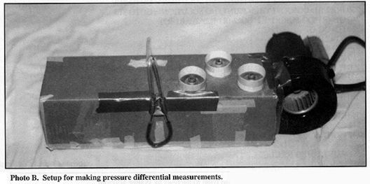
This is, of course, a "home-built" amplifier. The blower provided for cooling is a surplus item, rather common among builders. The cooling flow is specified in the data sheet (see table 1) in both CFM and the delta-P across the tube in inches water gauge, or w.g. Most of us couldn't make an accurate flow measurement, but we can make quite accurate pressure differential measurements.
This is accomplished by making a trial. Select a cardboard box large enough to accommodate both the blower and the number of tubes; in this case, three (see photo B). In the photo, the home-built manometer, constructed of TygonTM tubing, is visible on the side of the box. Red vegetable dye helps define the liquid levels. With both blower and tubes in place, start the blower and measure the distance between the surfaces. The minimum flow required depends upon the actual plate dissipation (photo B). A simple ruler is all you need to measure the difference in inches. In this amplifier, one-quarter inch would suffice; the elevation of Silver City is at 7,000 feet asl. The 10,000-foot reading is , therefore, appropriate.
The power supply
The power supply used is one built originally for the 4CX1200 (see Figure 3). Both the plate and screen voltages are adjustable. Mating connectors for each of the amplifiers are available, allowing it to be used on either amplifier. The screen-supply rectifier uses a "tuned choke" (not the capacitor around the filter choke). This is resonated at 120 Hz, the ripple frequency. Screen voltages must be steady. The use of a tuned reactor relieves the operator builder from having to construct a full-fledged voltage-controlled screen supply. All voltages are available from the supply, including the 24 volts DC required by the relays. Acknowledgment We wish to acknowledge the help and counsel received from Dick Linari, W0YXM. He has been, in this and countless other efforts, a valuable source of knowledge and inspiration.
References 1. Dean Battishill, W5LAJ, "The Care and Feeding of the 4CX1600B," Communications Quarterly, Spring 1998, page 91.
Bibliography 1. M. Walter Maxwell, W2DU, Reflections, The American Radio Relay League, Newington, Connecticut.
Figure 1. Schematic diagram (size: 49k)
Figure 2. Below
Figure 3. Power supply and protective circuits schematic (size: 145k)
Table 1. Minimum cooling air-flow requirements
Figure 2. Program for basic p1-network calculations from Reflections by Walter Maxwell.
5' ********************************************************************
10'* Qo-BASED PI-NETWORK CALCULATIONS BY W5FD *
20'* *
30'* CALCULATING PI-NETWORK REACTANCES USING W5FD EQUATIONS BASED *
40'* ON ACTUAL CIRCUIT OPERATING Q (Qo). *
60'* FILE NAAME : PINET Edited by W2DDU 2-21-89 *
61'* *
62'* EMENDED 9-8-91, W7DHD(Lines 320+) *
70'* *
80'* SEE W5FDS QST ARTICLE, AUGUST 1983, P23. SEE ALSO CORRECTIONS,*
90'* "FEEDBACK," QST, JANUARYY 1984.
100'*******************************************************************
110 CLS
120 X1=0:XL=0: R1=0:R2=0:Q1=0:Q2=0
130 INPUT "R1";R1
140 INPUT"R2";R2
150 INPUT "Qo", QO
160 IF(R1*R2*QO)<=0 THEN PRINT "NOT A P1 NETWORK";GOTO 310
170' SPECIAL CASE WHERE R1=R2
180 IF R1=R2 THEN X1=(2*R1)QO:X2=(2*R2)QO:Q1=QO/2
190 IF R1=R2 THEN XL=(R1*QO)/(Q1*Q1+1):GOTO 290
200 IF ABS ((QO*QO+1)-(R1/R2))<.01 THEN PRINT"L NETWORK"GOTO
310
210 IF ABS ((QO*QO+1)-(R2/R1))<.01 THEN PRINT "L NETWORK":
GOTO 310
220 IF R1/R2>Q0*Q0+1 THEN PRINT "NO SOLUTION" GOTO 310
230 IF R2/R1>QO*QO+1 THEN PRINT " NO SOLUTION ": GOTO 310
240 Q1=(R1*QO-SQR(R1*R2*QO^2-(R1-R2)^ 2))/(R1-R2)
250 Q2=QO-Q1
260 X1=R1/Q1
270 X2=R2/Q2
280 XL=(R1*QO)/(Q1*Q1+1)
290 PRINT TAB (3)"R1"TAB (14) "R2"TAB(23) "QO"TAB(33)"Xcl"TAB(45)"Xc2"TAB(57)"XL"
300 MS="####.# ####.# ##.# ####.# ####.## "
310 PRINT USING MS;R1,R2,QO,X1,X2,XL;PRINT;PRINT
320 INPUT "Enter frequency in Megahertz";F:PRINT:PRINT
330 W=2*3.14159*F*1000000!
340 C1=1/(W*X1):C2=1/(W*X2):L=XL/W
341 C1Á*1E+12:C2=C2*1E+12:L=L*1000000!
342 PRINT: C1,pF C2, pF L,UH"
350 NS="####.# ####.# ####.##
351 PRINT USING N$;C1,C2,L
352 END
Table 1. Minimum cooling air-flow requirements.
| sea level | 10,000ft. | |||
|
Plate dissipation |
Air flow |
Pressure Drop |
Air flow |
Pressure Drop |
**The information provided in this application note is intended for general design guidance only. The user assumes all responsibility for correct and safe usage of this information. Svetlana Electron Devices does not guarantee the usefulness or marketability of products based on this material.