
No.54
Broadcast/Communications
![]()
Extending the Life of Power Grid Electron
Tubes
By: B-N "Bob" Alper

 This
document will identify the failure mode of many vacuum electron tubes and discuss
ideas and recommendations for reducing the chances for failure and, in other
cases, for ameliorating situations that ultimately cause premature failure.
This
document will identify the failure mode of many vacuum electron tubes and discuss
ideas and recommendations for reducing the chances for failure and, in other
cases, for ameliorating situations that ultimately cause premature failure.
GENERAL
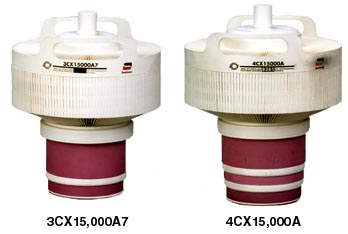
In order to have a clearer understanding of power grid electron tubes,
pictures of a Svetlana 3CX15,000A7 triode and a Svetlana 4CX15,000A tetrode
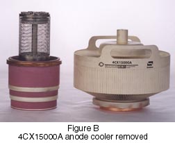
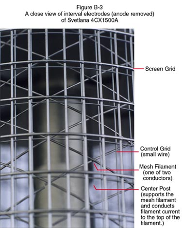
are shown in Figure A. Figure B shows the 4CX15000A anode cooler removed.
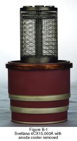
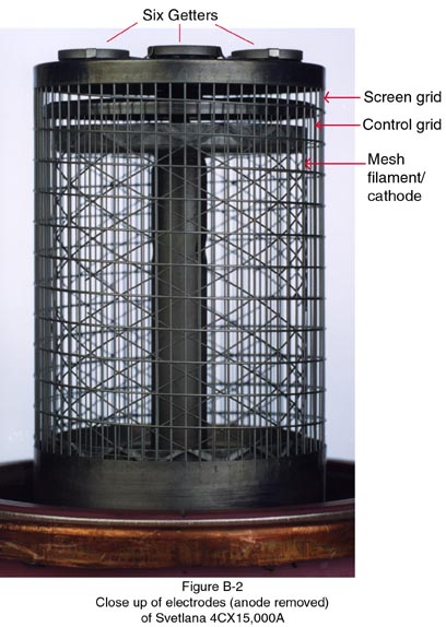
Figures B-1, B-2, and B-3 show internal details of the 4CX15000A. The internal
tube construction in the case of a tetrode consists of a cathode, control
grid, and screen grid. The cathode, a mesh filament, is cylindrical in
shape, and is formed in the manner of a woven basket. This type of cathode/filament
structure is known as a basket filament and more commonly known as a mesh
filament. The mesh filament is supported at the bottom on a cone, which
extends through the vacuum envelope for contact to the external circuitry.
At the top, the mesh filament is supported with a rigid vertical support
rod, which forms the other electrical terminal for the filament and also
provides firm support. The electrical and thermal conduction path from
this rod extends to the outside of the tube envelope via the central contact
areaa on the base structure. The electrode next to the cathode is the control
grid. This electrode is not woven in the same way as the mesh filament.
It consists of a series of vertical wires around the periphery of the grid,
which are supported by a continuous helix from the bottom of the grid to
the top, spot welded to the vertical wires. The next electrode is the screen
grid. It is constructed in the same way as the control grid; that is, a
series of vertical wires supported by a shallow helix. The outermost electrode
is the anode which has been removed from figures B1 and B2, so that the
internal structure may be seen. Of course, in the case of the triode, Figure
A, there is only one grid, the control grid. Note the insulator at the
top of the assembly in Figure B2. This insulator provides support for the
Screen Grid and rests on top of the basket filament. The washer shaped
devices on top of the element in Figure B2 closest to the anode, are getters.
The getters are incorporated in the tube structure to maintain low gas
pressure. They interact chemically with any gasses which may be liberated
from internal material by overheating. The getters are inactive while the
tube is on the shelf. However, when the tube is in operation and the internal
electrodes are then operated normally, the getters increase in temperature
the high temperature activates the getter, so that the interaction of removing
gases from the vacuum envelope continues during operation.
The internal construction of the 3CX15000A7 is similar with omission of details associated with the screen grid.
FAILURE MECHANISM
1) HEAT- Excess Heat is the single most detrimental environmental condition
for any electronic component. This is certainly true for Power Tubes. Excessive
heat is caused by inadequate cooling or excessive electrical dissipation values
in the tube electrodes. Therefore, it is ablsolutely essential that every effort
be made to provide the specified cooling to a power grid tube. Regular maintenance
is critical; clean the air and liquid filters, lubricate motor blower and liquid
pump bearings, clean the air cooling fins, flush liquid cooling lines, etc.
When a tube is operated above its rated temperature, ceramic-metal seals may
give way, elements may weaken, sag, and short out, etc. The tube efficiency
is usually reduced, causing a further builup of heat, setting off a "downward
spiral."
 2)
LOW CATHODE EMISSION- This is usually caused by depletion of active cathode
material on the surface of the filament or cathode. In thoriated tungsten directly
heated cathodes, this material is the carbon that has been added to the tungsten
during factory processing of a new tube. This manufacturing process is known
as "carburization." The mechanism of the loss of carbon during operation
is usually referred to as decarburation. The result is a lowering of available
cathode emission as the surface carbon depletes. In a normal tube, increasing
RF drive will usually cause an increase in plate current. When the cathode emission
is insufficient, increasing RF drive will cause little increase in cathode current.
In many cases, when there is insufficient cathode, peak current capability due
to a loss of emission , plate current can appear in the normal range, depending
on RF drive, but efficiency will be low. Failure is usually non-catastrophic.
Poor emission may be detected, and catastrophic failure avoided, by observing
trends in regularly recorded log data.
2)
LOW CATHODE EMISSION- This is usually caused by depletion of active cathode
material on the surface of the filament or cathode. In thoriated tungsten directly
heated cathodes, this material is the carbon that has been added to the tungsten
during factory processing of a new tube. This manufacturing process is known
as "carburization." The mechanism of the loss of carbon during operation
is usually referred to as decarburation. The result is a lowering of available
cathode emission as the surface carbon depletes. In a normal tube, increasing
RF drive will usually cause an increase in plate current. When the cathode emission
is insufficient, increasing RF drive will cause little increase in cathode current.
In many cases, when there is insufficient cathode, peak current capability due
to a loss of emission , plate current can appear in the normal range, depending
on RF drive, but efficiency will be low. Failure is usually non-catastrophic.
Poor emission may be detected, and catastrophic failure avoided, by observing
trends in regularly recorded log data.
The other causes of excessive heat is excessive dissipation, beyond ratings, in the electrodes. For example, when the grid current is excessive, grid power dissipation is often exceeded and the grid overheats. When this overheating takes place, gas evolves from the grid material and leads to back ion bombardment of the cathode or physical warping of the grid or other failure mechanisms. Therefore, it is absolutely necessary to have adequate control over grid dissipation and adequate automatic and instantaneous protection for excessive grid dissipation. The failure mechanism described here for the control grid in power tubes also holds, in general , for other electrodes, including the filament, screen grid, and anode.
3) SHORTED TUBE ELEMENTS- Shorts in vacuum tubes will, of course, cause erratic equipment performance and most certainly, over time, will result in catastrophic failure. The shorts are usually observed by the continual opening of one or more overload relays and activation of indicator lights. Often, excessive gas in the tube will result in an internal arc, which has similar symptoms to an electrode short. The only certain method to distinguish between excessive gas and an internal shorts is to remove the tube from the transmitter. Shorted elements will show up as a DC resistance of several hundred ohms or less on an ohm meter. Only the R times 1 scale should be depended upon for detecting element-to-element shorts in vacuum tubes. Often, in large power tubes, leakage current over the inside surface of the ceramic will give an indication on a "megger" or a sensitive ohmmeter, but will not adversely affect performance of the tube in operation. A symptom of no cathode emission will exist if the heater or filament does not light. This symptom is obvious in the case of glass tubes; however, it is not always discernible in the case of metal ceramic tubes. In smaller transmitters, failure may not cause a fuse to open , but may cause components to be damaged, or cause overheating and a resulting odor. Sometimes, there will be a short in a tube, but only under 'hot' conditions. Then, of course, there will be no indication on an Ohmmeter.
4) NO CATHODE EMISSION- Broadcast and commercial communication transmitters will usually have a filament current meter, which will indicate an open filament . In smaller transmitters using ceramic tubes , an open filament is a little more difficult to detect. First turn on the transmitter and let it warm up for a few minutes. Then turn the primary power off, disconnect the primary power or at minimum- disconnect primary power by using the primary power breaker. Carefully gain access to the tube location and short the plate of the tube(s) to ground for safety with an insulated grounding device. Now, and only now, carefully feel the tube for warmth. The tube should have a warm feel to the touch. If there is more than one ceramic tube, in the transmitter, a comparison of the temperature of each tube may be made. Care should be exercised, as the filament in most ceramic tubes runs at sufficient temperature to cause a flesh burn.
 5)
OPEN TUBE ELEMENTS- It is possible to have an open connection, internal to the
tube. Such will usually be accompanied by other indications, such as meter indications.
However, once the symptom is observed, it becomes necessary to determine which
element is open. In the case of the control grid , there will be no grid current,
if there is usually grid current indicated on the meter. Also, without RF drive
on the tube, it will not be possible to control the plate current with adjustment
in the negative grid voltage. In the case of an open screen, no screen current
will be indicated on the screen current meter. Unloading of the plate RF output
coupling would normally cause an increase in screen current when the RF drive
to the amplifier input is normal. Screen current would still be absent, in the
case of an open screen.
5)
OPEN TUBE ELEMENTS- It is possible to have an open connection, internal to the
tube. Such will usually be accompanied by other indications, such as meter indications.
However, once the symptom is observed, it becomes necessary to determine which
element is open. In the case of the control grid , there will be no grid current,
if there is usually grid current indicated on the meter. Also, without RF drive
on the tube, it will not be possible to control the plate current with adjustment
in the negative grid voltage. In the case of an open screen, no screen current
will be indicated on the screen current meter. Unloading of the plate RF output
coupling would normally cause an increase in screen current when the RF drive
to the amplifier input is normal. Screen current would still be absent, in the
case of an open screen.
6) TUBE GASSING- The manufacturing process and factory processing of tubes today make obsolete some of the past procedures required of a purchaser, in order to keep a new, unused spare tube healthy. The likelihood of a properly sealed new tube being delivered gassy is remote today. There continues to be the chance that a minute air leak can occur in the envelope material, allowing the vacuum to deteriorate. Or, due to arcing, misuse, and/or overheating, gas trapped in material internally in the vacuum envelope is released. A gassy condition in a glass tube may visibly be identified by a bluish-pinkish-violet glow, inside the plate, usually extending to the cathode. In a ceramic tube, a gassy condition is much more difficult to identify. Typically a flash inside the tube can be seen through the ceramic, indicating an overload. The ceramic of a tube, operating in a resonant cavity often is not visible. All than can be observed are unusual current readings. And, of course, when the tube is replaced, all returns to normal. There is no one circuit that is agreed upon by a majority of the vacuum electronic engineers to measure gas. Most circuits measure a combination of gas, leakage current, and grid emission current.
PLACING A NEW TUBE OPERATION
Upon receipt of a shipment of a new tube, immediately inspect for damage or
other anomalies before placing in equipment or placing in the storeroom for
future need. Tarnish on the finish is not a matter of concern. Of concern, are
bent or broken parts, dents, chipped or cracked ceramic, or similar items. Measure
between all terminals with an Ohm meter, on the R X 1 scale. There should be
no continuity, between any of the terminals, except of course the filament.
Do not rely on a 'megger' or highly sensitive Ohmmeter such as VOM on the R
X 100 or R X 1000 scale. If there is time to place the tube in operation, this
should also be performed.
After inspection of the new tube, and completing it's warranty card (for mailing), the old tube should be carefully removed from its socket and visually inspected for unusual signs of discoloration, accumulation of dirt, or other signs of trouble. Do not rock the tube to remove or insert them in the socket. The socket should be carefully cleaned and inspected for broken parts, non-concentric finger stock, or finger stock temper, arc damage or burned parts. Damaged parts or the entire socket should be repaired or replaced, as necessary. When the new tube is plugged into the socket, and inspection should be made to insure that all visible contact surfaces are properly in contact with their appropriate connectors. Finger stock should be tight against the contact rings. Some engineers rotate the tube a quarter turn in its socket if the tube physical construction allows it. Such an action assists in making contact between the socket and tube connections. If the tube has flying leads, the connection posts should be inspected and cleaned. Nuts on flying lead connections should be tightened finger tight, then tightened with a torque wrench to the specified torque. Consult the transmitter manufacturer for the proper amount of torque. If a torque wrench is not available, then after finger tightening, not more than 1/8 turn additional shall be added using a wrench. Verify that the cooling system is in proper operating condition; air systems should have clean filters; liquid systems should be checked for conductivity and oxygen content. Check the flow rate.
If a filament voltage meter is a permanent part of the transmitter, now is a good time to verify its calibration. A good quality, recently calibrated, analog volt meter is recommended as the standard. The analog meter should measure the voltage at the tube's filament terminals on the socket. The panel filament voltage meter set accordingly. After turning on the filament, allow the tube to warm up at its nominal rated voltage for the amount of time that the manufacturer recommends for a brand-new, out-of-the-carton tube. Presuming this is not an emergency installation, it is recommended that this new-tube warm-up time be at least the manufacturer's absolute minimum recommended time. In any case Svetlana recommends at minimum, a 15-minute warm-up should be employed for a new out-of the-carton tube. The filament voltage should be rechecked and readjusted, as necessary, to the nominal value recommended by the tube manufacturer.
 Initial
application of plate power and initial tuning should be performed at a low transmitter
RF power setting. Once tuned at low power, if all tube electrical parameters
are operating within manufacturer's limits, transfer to high power operation
can be made. Again, operation of the power amplifier tube within the manufacturer's
electrical parameters should be verified to ensure proper operation.
Initial
application of plate power and initial tuning should be performed at a low transmitter
RF power setting. Once tuned at low power, if all tube electrical parameters
are operating within manufacturer's limits, transfer to high power operation
can be made. Again, operation of the power amplifier tube within the manufacturer's
electrical parameters should be verified to ensure proper operation.
Whenever a different tube of the same type is installed in an IPA or PA, transmitter adjustment procedure should always be performed. The same tube type from the same manufacturer often is different. The fine tuning (front panel adjustment) may not have the sufficient range for correct tuning. Therefore, after installing a tube and performing the recommended transmitter adjustment procedure, meter readings should be compared to those considered 'normal' by the transmitter manufacturer. Should the 'normal range' not be achievable, then the transmitter should be turned off and opened up to inspect the transmitter fine-tuning apparatus. If the fine tuning is at either extreme, the course-tuning adjustment should be made as directed in the transmitter manufacturer's instruction manual.
IMPROVING TUBE LIFE
It is possible to avoid most catastrophic tube failures not associated
with natural events or external influences beyond our control, such as
lightning strikes, primary power surges, large primary power fluctuations,
etc. Below are listed a few simple maintenance and operational actions
that Svetlana recommends to extend tube life.
1) Regular Large Primary Power Variations- Many transmitter sites are located in remote locations at the end of a long power line. If there are regular large variations in primary power, then corrective action should be taken. The preferred solution is a stiffer primary power source. In most cases this is not possible because of various reasons. Corrective action can be taken to stabilize the more important parameters such as the power tube filament voltage. Filament voltage variations that vary more than ± 5% can cause larger power tube life to be shortened by 50% or more. A magnetic regulating-type transformer should be considered for the filament power supply line. Locating a convenient place for installing the transformer is important, prior to its purchase. Of course, other electronic regulators are acceptable, though many may be more expensive.
2) Cooling Maintenance- Re-emphasizing an earlier statement, adequate
cooling is one of the most important ways to extend tube life.
(a) Air Cooling- Regular cleaning or replacement of air filters is extremely
important. The maintenance schedule will depend on the cleanliness of the
air used for cooling. Periodically inspect and clean the blowers. Dirt
on the blades can materially reduce the quantity of air, causing the tube
temperature to rise but often not sufficient to activate the air failure
sensor. Many transmitter engineers permanently mount a well-calibrated
thermometer in the exit cooling air stream of tubes. Some monitor both
intake and exhaust air temperature. Air temperature as well as cleaning
and replacement of air filters should be recorded in the station log, which
should be reviewed regularly.
(b) Liquid Cooling- The water supply may be closed-loop or open-loop. Svetlana
recommends a closed-loop system. The water should be clean, have low conductivity
(0.5 megohms across the purity loop), and should be deionized and demineralized.
Where the mineral content and oxygen content are high, special filters
are recommended to reduce contaminants in the water. Filters should be
replaced when the resisitivity of the purity loop falls below the 0.5 meg-ohm
value. The oxygen-removal filter should be replaced whenever the dissolved
oxygen content rises above 0.5 parts per million. A typical filter to remove
solids, for use in a liquid-cooling system, might be a filter mesh of 60
installed at the pump outlet. Where the heat exchanger is located outdoors,
environmental conditions may dictate preventing the water from freezing.
The preferred method is to heat the water. However it may be necessary
to use a mixture of water and ethylene-glycol or other chemicals to prevent
freezing and allow operation below freezing temperatures. It should be
kept in mind that the thermal capacity of the ethylene-glycol and water
mixture is less than that of water alone. Therefore, an increase in the
pressure drop across the tube to increase the flow rate will be required
to obtain the same cooling capacity as water alone. Table
1 provides several aqueous solutions of ethylene-glycol versus the
freezing point of the solution. Svetlana recommends a maximum use of 52%
ethylene-glycol solution in a cooling system. A liquid cooled system that
is in use on a 24-hour basis should be drained and have the water replaced
once each year. At that time, the old water should be examined for algae
and mineral deposits.
Table 1
|
Percent Ethylene Glycol
0 |
Percent Water
100 |
Freezing Point (F. Degrees)
32 |
Should algae be found but no other impurities, the water reservoir should be drained and refilled with clean distilled deionized water to which one gallon of vinegar has been added. After an hour of flushing, the vinegar solution should be drained and the reservoir refilled with distilled, deionized water. A small amount of algaecide may be added to prevent algae buildup.
 Greasy
deposits due to leaky pump seals and oil reservoirs may be flushed with slightly
soapy water to which a few cubic centimeters of denatured alcohol is added.
Calcium deposits may be loosened and flushed by using a 5% to 10% solution of
hydrochloric acid or a 15% to 20% solution of citric acid. Repeated flushing
may be required to free algae, greasy deposits, or calcium deposits particularly
if the residue is located in crevasses in the system's narrow cooling channels
of the tube anode cooling jacket.
Greasy
deposits due to leaky pump seals and oil reservoirs may be flushed with slightly
soapy water to which a few cubic centimeters of denatured alcohol is added.
Calcium deposits may be loosened and flushed by using a 5% to 10% solution of
hydrochloric acid or a 15% to 20% solution of citric acid. Repeated flushing
may be required to free algae, greasy deposits, or calcium deposits particularly
if the residue is located in crevasses in the system's narrow cooling channels
of the tube anode cooling jacket.
This procedure prevents build-up of particles and corrosion in the cooling channels of the tube. When a layer of material builds up on the cooling channel walls, the efficiency of the heat removal system is greatly reduced. Ultimately, temperature will rise above the rated maximum, resulting in tube failure.
3) Proper Tuning Not enough can be said about operating the tube within the manufacturer's specifications and following the transmitter manufacturer's instructions for proper operation and tuning of the transmitter. All adjustments associated with power amplifier tubes, whether in an IPA or PA, shoud be performed at nominal rated filament voltage. Neutralization and efficiency adjustments should be made and verified at nominal filament voltage. If a tetrode is being tuned, the maximum RF output should occur precisely at maximum screen current, if the stage is properly neutralized. If the screen current in a tetrode is too high, output coupling must be increased. In a triode, keep the control Grid current below the allowed maximum by reducing RF drive and /or increasing output loading. If a triode is being tuned, control grid current should peak at the maximum RF output tuning if the stage is properly neutralized. Control grid current should not remain higher than that recommended by either the transmitter manufacturer or the tube manufacturer. If the control grid current is too high, the appropriate combination of adjustments between RF drive and RF output coupling must be made. Again, following the transmitter manufacturer's instruction book is mandatory.
4) Degassing- After considerable time on the shelf some glass transmitting tubes have a tendency to show signs of gas. This is less likely with ceramic tubes, since Kovar is not used in the seal. Ceramic tubes may show signs of gas if overheating has occurred. At first turn-on, the internal gettering material can be activated in either tube type by operating the tube with filaments on and no other voltage for a considerable length of time. Large tubes require five or six hours of operation. Smaller tubes (due to their smaller volume) require less time.
5) Filament Management- In a properly designed transmitter, long term tube life is usually limited by the emission of the filament, barring external and environmental influences. Most large power tubes use a thoriated tungsten filament. The emitting material on the surface of the filament wire is usually carbon. The process of adding this emitting material to the filament was described earlier, and is performed while the envelope is evacuated. It is one of the final processes before the tube is pumped, then sealed to the environment.
During normal operation, the carbon is reduced or burned off as the filament is heated and electrons stream to the anode. This type of filament/cathode operates in a temperature-limited regime. That is, once a temperature is reached, enough electrons are emitted to satisfy the design performance of the tube. Increasing the temperature beyond this point will result in minimal improved performance of any parameter, including an increase in RF output. Operating the filament at these higher temperatures will greatly reduce the length of time the filament will produce enough electrons to satisy the tube design performance.
 Figure
1 is a composite chart showing the effect on tube life of increased filament
power for a thoriated tungsten filament. The usual case is to design a thoriated
tungsten filament for operation at or near 2000 degrees K. Certain applications
require high efficiency emission at an expected reduction of tube life. For
most broadcast and communications amplifier applications, operation at a constant
filament voltage is desired. Further, proper operation depends on drawing the
electrons from the space cloud that surrounds the cathode (filament). Therefore,
if the cloud is significantly reduced by consistent over-current, electrons
are drawn directly from the cathode (filament), causing loss of cathode material,
resulting in significantly shortened life. Conversely, lowering of filament
power too far causes the tube cathode (filament) to run too cool, resulting
in degraded tube performance. There is often damage to the tube cathode surface
when operating from too cool a cathode. It should be understood that filament
temperature is not the only significant factor affecting tube life. A rise in
gas pressure also reduces tube life. An increase in gas pressure occurs when
tube elements are overheated (operated at higher than rated temperatures) beyond
that temperature at which the tube was processed during manufacture. If the
tube is operated at moderately cool temperatures or if the filaments are operated
without plate voltage for long periods of time, gas pressure will also rise.
A ± 5% variation in voltage is usually specified by the tube manufacturer.
However,smaller power tubes often use slower heating cathode type filaments
which usually tolerate ± 10% voltage variation. Therefore, unregulated
power may be used for filament power.
Figure
1 is a composite chart showing the effect on tube life of increased filament
power for a thoriated tungsten filament. The usual case is to design a thoriated
tungsten filament for operation at or near 2000 degrees K. Certain applications
require high efficiency emission at an expected reduction of tube life. For
most broadcast and communications amplifier applications, operation at a constant
filament voltage is desired. Further, proper operation depends on drawing the
electrons from the space cloud that surrounds the cathode (filament). Therefore,
if the cloud is significantly reduced by consistent over-current, electrons
are drawn directly from the cathode (filament), causing loss of cathode material,
resulting in significantly shortened life. Conversely, lowering of filament
power too far causes the tube cathode (filament) to run too cool, resulting
in degraded tube performance. There is often damage to the tube cathode surface
when operating from too cool a cathode. It should be understood that filament
temperature is not the only significant factor affecting tube life. A rise in
gas pressure also reduces tube life. An increase in gas pressure occurs when
tube elements are overheated (operated at higher than rated temperatures) beyond
that temperature at which the tube was processed during manufacture. If the
tube is operated at moderately cool temperatures or if the filaments are operated
without plate voltage for long periods of time, gas pressure will also rise.
A ± 5% variation in voltage is usually specified by the tube manufacturer.
However,smaller power tubes often use slower heating cathode type filaments
which usually tolerate ± 10% voltage variation. Therefore, unregulated
power may be used for filament power.
Continuously operating a large power tube at +5% filament voltage can reduce the longevity by as much as 50%. Therefore, we want to operate the filament at a voltage only as high as necessary to provide the desired full performance. Stated another way, power tubes should be operated within all electrical specifications, except filament voltage. The filament should be operated at the lowest voltage providing the rated specified equipment performance.(Please refer to Figure 1.)
To accomplish this proceed as follows:
(1) Set the tube filament voltage to the nominal value on the tube manufacturer's
technical data sheet. This can also be found in the transmitter manufacturer's
Operating Instruction Manual.
(2) Tune the transmitter in accordance with the transmitter manufacturer's
instructions. When tuning is complete, check all tube electrical operating conditions
to ensure operation within specification. Usually, this may be accomplished
using the meters on the transmitter. However this is not always true. Two areas
often requiring further investigation are tube grid current and filament voltage.
Most transmitter manufacturers include a front-panel filament voltage meter
and a front panel filament adjustment that usually has limited range. However,
these filament voltage meters are often out of calibration. Also, many have
an electrical circuit to adjust calibration to compensate as components change
with age and temperature. The filament voltage panel meter should be checked
for accuracy against an iron vane voltage meter, or another meter of known accuracy.
Caution is advised in using digital VOM as the magnetic fields and RF fields
in a transmitter can impair the accuracy of the solid-state circuitry in these
meters. Further, digital VOM's often read incorrectly if the filament voltage
wave form is not sinusoidal (such as is found when a magnetic regulating device
is used). Once satisfied that the transmitter is properly tuned, if the power
tube is new, out-of-the-box, the transmitter should be operated at rated nominal
filament voltage for 150-200 hours before proceeding. This allows the tube to
settle into its operating parameters, and absorb any out gassing that remains.
After the tube has operated 150-200 hours and is settled in, and one is satisfied that the transmitter power amplifier is properly tuned within tube ratings then, using the filament voltage adjustment, reduce the filament voltage 1/4 volt at a time while observing the RF power output. A setting of the filament voltage will be reached where a small decrease will result in a large decrease in RF output or, the rated output is no longer achieved. The curve of power output vs. filament power shown in Figure 2 is typical. The filament voltage should just be increased until rated RF power is achieved. This is the minimum filament power point for rated power. The filament voltage should be further increased by 0.1 or 0.2 volts to allow for primary power line variation. The increase should be 0.2 volts for remote transmitter operation. While not easy to accomplish at a remote transmitter site, the transmitter should be checked 24 to 48 hours later for stable operation.
 There
after the filament voltage should be checked in this manner every 30 days, to
ensure proper operation. During each check , the tube filament should be returned
to recommended nominal value for tuning the transmitter, and then, AND ONLY
THEN, should the procedure be used to adjust for minimum filament power.
There
after the filament voltage should be checked in this manner every 30 days, to
ensure proper operation. During each check , the tube filament should be returned
to recommended nominal value for tuning the transmitter, and then, AND ONLY
THEN, should the procedure be used to adjust for minimum filament power.
If the equipment being serviced is a standby transmitter and the filaments are normally in the standby mode, a decision may be necessary to determine the best filament adjustment. The standard filament management procedure described above, may be selected and the standby transmitter adjustments re-optimized during each scheduled maintenance visit. The standby transmitter may also be operated at a flat reduction of 4% to 5% filament voltage, with the understanding that full RF output may or may not be obtained upon activation; however service would continue upon standby transmitter activation.
6. Grid Protection
Too often the transmitter manufacturer will not include a grid current meter. Usually the manufacturer of a triode amplifier will include a plate current meter and a cathode current meter. The grid current can, of course, be calculated by subtracting the plate current from the cathode current. While this is inefficient, it does allow access to the grid current information. However some method of directly monitoring grid current and providing sensitive and accurate protection based on grid current is an absolute necessity for adequate tube protection.
7. Logging
Regular logging of selected important meter readings will avoid most catastrophic
failures not due to environmental circumstances, such as lightning or power
line problems. Svetlana Electron Devices recommends logging the following power
tube parameters at least once every 30 days.
1. power output
2. plate power input (also record plate voltage)
3. plate current
4. screen current (if the PA or IPA is a tetrode or pentode)
5. grid current
6. tube exhaust air temperature
7. filament voltage
8. running-time meter
9. primary line voltage
10. RF output power
11. Reflected power or VSWR of the transmission line/antenna system.
12. Routine or non-routine maintenance performed.
These recorded tube parameters can convey important trend information. For instance, if RF output power is down after complete retuning and assuring proper RF excitation and all else is normal , the electron tube may be losing peak emission. At this point, a small increase in filament voltage of 0.1 to 0.2 volts should be made. The small increase will likely cause the RF power to rise. If the RF power does increase, then the procedure described above under 5.Filament Management should be followed. Once the new filament operating voltage is determined, the tube technical data sheet should be consulted to determine that the filament voltage operating point is within the tube manufacturer's specification. If the filament voltage is higher than the specification, a close watch on the tube operation should be maintained to optimize filament emission for the remainder of the life of the tube.
It is not unusual to find that a tube's filament voltage may require increasing. Often , a tube will settle in and operate for an extended time at this new filament voltage setting. As the filament voltage is increased, and it becomes higher than the maximum specified to achieve proper RF performance, failure is approaching, however the tube may have thousands of hours remaining life at higher than specified filament voltage. Under these conditions, the anticipated failure will likely be a "soft failure," and not a catastrophic failure. The new filament voltage setting should be recorded in the transmitter log. Over a period of time the transmitter operator can observe a trend that can most likely lead to tube replacement.
Another symptom one might observe in a log is increasing screen current, in a tetrode or pentode stage, or increasing grid current in a triode stage. Either, when accompanied with lower plate current and lower RF output power, may indicate that the output coupling may have changed or something has changed in the following stage or antenna system.
Svetlana Electron Devices, Inc. will update this Techincal Bulletin from time to time. You, our customers, are encouraged to submit tips, guidelines, and experiences that you have foud helpful in your career of working with transmitters.
If you wish you will be given credit for your submission(s) of information; however Svetlana Electron Devices, Inc., reserves the right to use the submission without restriction. Much of the information included above is not presented as original information. Most of the information presented has been previously published in a variety of books. The author of this booklet gives credit to all these excellent sources.
**The information provided in this application note is intended for general design guidance only. The user assumes all responsibility for correct and safe usage of this information. Svetlana Electron Devices does not guarantee the usefulness or marketability of products based on this material.