
No.57
Hi-Fi Audio
SV300B
![]()
30 Watt Push-Pull with Svetlana SV300Bs
By: Kevin Kennedy
Article as first appeared in Vacuum Tube Valley, Issue 12, Summer 1999
Introduction
I think many, if not most, of the sonic benefits of single ended operation can be realized in a DHT push-pull amplifier, as long as very high quality iron is employed and global feedback is not. Power supply performance is a crucial ingredient in the overall sonic performance of an amplifier, and for this reason I employed tube based voltage regulation in this design. The amplifier design is fully differential in nature, and may be driven by either a balanced source or unbalanced source.
Although output power is only 30Wrms, these amplifiers sound much more powerful with my planar speakers than I have any right to expect. I must attribute a lot of this to the excellent performance of the SV300Bs, and the fine quality of the Citation II output transformers used. This design is targeted at those who own moderately inefficient high end speaker systems, but nevertheless recognize the seminal virtues of DHT triode amplifiers, and in particular the virtues of the 300B tube family.
My goal was to design an amplifier of high resolution, accuracy, and tonal correctness without the harshness of some designs or the euphony of others. Equally important is the fact that no exotic parts except for the Citation II transformers are required for this level of performance, and that the design is simple enough to allow replication by almost anyone skilled with a solder iron and a few hand tools. No exotic test equipment is required to get them operating, just a simple multimeter as a minimum.
I chose the 300B output tube because I feel it is hard to better its sonic virtues and exemplary electrical performance. I also wanted to avoid extreme drive and supply voltage requirements for this design. I chose the Svetlana 300B because it performs electrically and sonically about as well as the few vintage WE300Bs I have come across, and at less overall cost. It also exhibits exceptional consistency, bias stability, and quality of construction.
The amplifiers are extremely neutral, detailed, and open. Perhaps the best I have yet heard in my own system. Imaging and sound stage depth are amazing, microdynamics, and dynamics seem just right. Clarity of reproduction is extremely pleasing. Tonal balance is pleasingly neutr a detail freak. Tonal balance is pleasingly neutral with no particular emphasis to any part of the spectrum.
Amusingly, I have started to notice some not so subtle, but previously inaudible, shortcomings in a few of my favorite recordings, such as small extraneous noises: electrical clicks and pops, studio or venue noise floor. I listen to a pop, funk, and grunge rock, and these amplifiers seem to be at home with it all, and are particularly good at capturing the subtleties of female vocalists, and the natural timbre of acoustic, percussive and wind instruments.
Technical Description
The topology employed is conventional in most senses, as the goal was to keep the design as simple as possible without compromising within reason on bandwidth or output tube drive capabilities. Available gain is such that 1.0Vrms of unbalanced drive, and 500mVrms balanced drive should be sufficient to drive this amplifier to full output, making this design suitable for use with active as well as some passive pre-amplifiers, and buffered designs having no actual voltage gain.
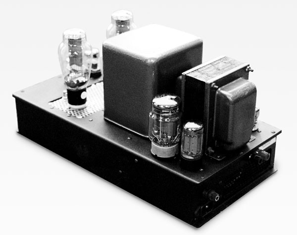
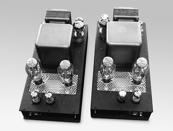
These units were built as monoblocks, and are completely self-contained. The power supplies and other required circuitry are on the same chassis with the amplifier circuitry. Layout is crucial, and for this reason the power supplies are located on the rear area of the chassis, the output stage towards the middle, and the input and driver stages at the front. All AC wiring near sensitive circuitry is fully shielded to keep hum and noise away.
The differential amplifier tubes and input sockets are deliberately located to one side of the chassis, far way from the AC switch. The chassis as designed are fairly compact at 8.5" wide x 17" long. In order to make this practical, careful attention was paid to ventilation. The 300Bs are mounted on a perforated stainless steel platform which is mounted in a rectangular cutout in the chassis. Insurance against setting the amplifiers down on a soft surface (such as carpet) is provided by ventilation apertures in both ends of the chassis. These apertures are protected by a perforated metal sheet, and as a result, these amplifiers run very cool. However, unless you are prepared to make similar provisions, the use of a considerably larger chassis is recommended to avoid compromising the life of the 300Bs and other components.
The first amplifier stage is a differential amplifier (long-tailed pair) employing a 6SL7GT, and operating at a quiescent current of 1mA per section. No current source is employed as this runs counter to my philosophy of keeping the circuit path as simple as reasonably possible. In previous experiments it became clear that using a simple large valued resistor in the long tailed pair only reduced common mode rejection by a few dB, and had no measurable impact on stage balance, provided that the tail resistance is large relative to the internal cathode resistance. A combination of fixed bias (represented by the tail tied to the -200V rail) and self bias provided by the individual cathode resistors tied to the tail resistor, provides a reasonable measure of dc balance even with some unmatched tubes. Some minimal tube matching is recommended. Stage gain is typically 22dB with unbalanced drive, and 6dB greater with balanced drive.
The differential driver stage is direct coupled to the preceding stage, and like the input stage relies on a combination of fixed and self bias for the same reasons as outlined previously. Overall gain in this stage will be in the range of 14dB. Quiescent current is 3.4mA per section, and the total output current from the driver stage at clipping is approximately 0.35mA peak, excluding the loading due to miller capacitance in the 300Bs (Miller + grid to filament capacitance is estimated to be 70pF.) Full signal bandwidth at this point is 80KHz @-3dB, and 170Vpp per plate, without the 300Bs installed. Cathode followers are not employed, as I felt that the standing current in the 6SN7 differential driver stage should allow for sufficient output current to drive both the Miller capacitance of the 300B as well as the current requirements of the 221K grid bias resistors.
The output stage employs a pair of Svetlana 300Bs in push-pull, operating in class AB1 at a quiescent current of 80mA per tube. Fixed bias is employed, and each tube has its own filament winding to allow for easy bias measurements. AC heating is employed simply because I prefer the sound of DHTs that way, and push-pull operation will cancel most of the hum so induced, as the filament hum is a common mode signal.
The Citation II output transformeers employed are excellent quality devices with a primary impedance of 3.3K ohms. The Peerless S-275, by Magnequest, would be another good choice based on performance specifications, and has a primary Z of 4K. A less expensive alternative is the Brooklyn B23 also with a 4K primary impedance, and the least expensive alternative is the Hammond 1650K/KP. The Bartolucci 123, with a primary Z of 3K, may produce slightly more output power, with a possible small penalty in terms of THD.
There is no global feedback used in this design because it is typically detrimental to sound quality. One of the key issues in this application is that the primary inductance should be quite high relative to the plate to plate impedance. Values of 150H and above are not unreasonable to prevent excessive distortion at low frequencies.
There are three regulated supplies in this design: two tube based high voltage regulators, and one solid state regulator for the driver and input tube filaments. Power supply design is crucially important to the performance of this (or any) amplifier, and a lot of attention was devoted to this issue. These supplies offer excellent performance in all areas relevant to audio amplifier design: tight regulation, wide bandwidth, low output impedance - just a few ohms at dc, good to excellent ripple rejection, and low noise.
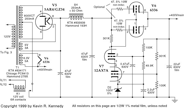
The regulated plate supply offers a continuous capacity in excess of 250mA, the limit of the 5AR4 rectifier chosen - perhaps two might be paralleled if desired for greater capacity. The raw supply is rectified by a single 5AR4 and then applied to a pi filter consisting of two 47uF film capacitors and a 5H choke. The pass element is a parallel strapped 6336/A/B, and the error amplifier is a 12AX7A connected in a cascode configuration for high open loop gain, and good voltage standoff ability. Output voltage is +400vdc, with loadline regulation of better than 1%, and ripple levels of 2.5mVpp or less under load. Output impedance calculates to 2 or less from dc on up, and is capacitor dominated at high frequencies. No electrolytic capacitors have been employed in this regulator. Interaction between the power amplifier and its supply has been greatly reduced by virtue of its low output impedance.
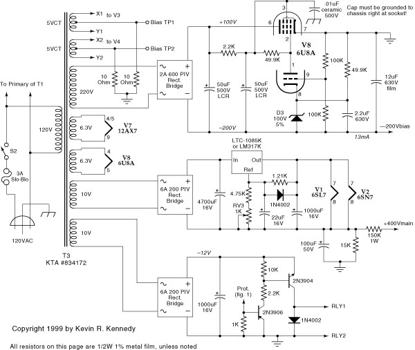
The bias supply is based on a single 6U8A, fed by a 600PIV solid state bridge rectifier. The pentode section functions as the pass element, while the medium mu triode serves as the error amplifier. The pentode pass element's screen supply is heavily filtered to allow the pentode to provide a high level of ripple rejection prior to the application of loop feedback. The regulator can source up to 20mA at 200V for the output tube bias, input stage bias, and driver stage negative supplies. Ripple and noise are typically < 2mVpp, and warm up time is typically less than 40 secconds, handily beating the main plate supply time constant.
Note that protection against bias supply failure and delayed B+ during bias supply warm up should be provided as shown in the schematics. Optionally this relay may be installed in the primary leads of the main power transformer if desired. However, if you contemplate substituting a 5U4 for the 5AR4 specified, this may cause problems with the 6336 cathode stripping. If this feature is omitted altogether a 300mA fuse must be installed in the center tap lead of the plate supply transformer.
Most of the tubes have dedicated filament windings on their respective supply transformers, and all tube filaments including the 300Bs operate on AC, except for the driver stages which have a tightly regulated 6.3Vdc filament supply.
Amplifier Specifications
Voltage Gain: 20dB unbalanced, 26dB balanced
Input Impedance: 68.1Kohm Balanced or Unbalanced Inputs
Frequency Response: + or - 0.5dB 20 - 20KHz small signal
Power Bandwidth:
1W : -3dB @ 33KHz
25W: -3dB @ 33KHz
Harmonic Distortion: 1W: < 0.16% thd @ 100Hz, 1KHz,10KHz.
10W: < 0.35% thd @ 100Hz, 1KHz, 10KHz.
25W: <1.0% thd @ 100Hz, 1KHz, 10KHz.
Noise: < 1mVpp, typical into 4 ohms
Maximum Power into 4 ohms: 31Wrms at 2% thd and 1kHz
Notes: All measurements performed with unbalanced RCA input mode selected, and Citation II output transformers.
Construction & Testing
This design includes circuits that operate at lethally high voltages, and extreme caution in the construction and testing of this, or any tube amplifier is required! The death you prevent might be your own. No liability by the author or Vacuum Tube Valley will be assumed for injuries or property loss while constructing or using this circuit.
Please note that this design is provided for the use of hobbyists only. No commerical use of this design is permitted.
In terms of constructing this amplifier it may be useful to think in terms of individual circuit blocks. There are actually five blocks to consider: the first block is the 300B based output stage, the second block is the input stage (perhaps the most critical of all), the third block is the +400Vdc regulated supply, the fourth block is the -200Vdc bias supply, and the fifth block is the dc filament regulator, filament supplies and fault protection. Individual circuit blocks may be tested before proceeding to the next stage if desired. Testing of the actual amplifier circuitry requires that the power supplies be built and debugged first.
Amplifier Circuit Theory
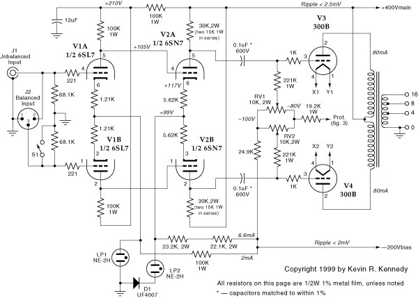
Input Stage, Driver Stage, Neon Clamps, 300B Coupling & Bias Circuitry
The first and second blocks are present in the first schematic (Figure 1) and consists of the 6SL7 based balanced input stage, a +200V supply decoupling capacitor, the 6SN7 based driver stage, two neon lamps which serve as protective clamps for cathode insulation protection in V1 and V2 during warm-up, and the 300B push-pull output stage. Neon lamps LP1, LP2, and diode D1 must not be omitted! Immediate destruction of the cathode to filament insulation in V1 and V2 will result. These devices serve to clamp the cathodes to safe voltage values, during filament warm up. LP1 ceases conduction once V1 warms up to the point where normal plate current is flowing, and D1 prevents the neon LP2 from conducting during normal operation of V2 by becoming reverse biased. These neon lamps should extinguish once the tubes warm up.
The 6SL7 first stage functions both as a phase splitter and provides most of the voltage gain in this amplifier. The plate voltage on this stage should be approximately 105V + or -5%, and should be matched to within + or - 2.5%. R103 and R104 provide both a limited amount of cathode degeneration and help to correctly bias V1. This stage may be tested by removing V2 at which point the plates should be capable of swinging at least 40Vpp per plate, and should swing 20Vpp per plate with 1.4Vpp at the RCA input, with switch S1 in the closed position.
The second stage consists of a 6SN7 running as a differential amplifier, and primarily serves to develop the large voltage swings required to drive the 300B output tubes to full output. R113 and R114 are tied to the negative bias supply and act as a 4W power resistor. (This resistor dissipates ~ 2W in normal operation) The purpose of the connection to the bias supply is to allow the use of a large common resistance to assure good AC balance in this stage despite the presence of the largish 5.6K cathode resistors which provide some self bias in addition to the fixed bias created due to direct coupling the first stage to the driver stage. This provides adequate voltage swing at the grids of the 6SN7 to assure linear operation at the maximum plate voltage swing required. This stage should swing at least 170Vpp linearly per plate before any observable clipping occurs, and 180Vpp is typical. Bandwidth at this stage should be greater than 80kHz @ -3dB without the 300Bs installed.
The output stage consists of a pair of Svetlana SV300B in push-pull driving an output transformer of at least 3K primary impedance. The output stage is capacitively coupled to the 6SN7 driver stage, and employs fixed bias. Each 300B has its own independent bias adjustment pot, the component values chosen allow an adjustment range of -80V to -100V, with -82V resulting in about 80mA (+400V plate) of plate current per tube. If necessary, resistor value may be decreased slightly in order to change the bias range if you cannot adjust the plate current to 80mA per tube. These component values were chosen to prevent destruction of the output tubes should the pots be mis-adjusted. Small, high quality film caps of 0.1uF -0.22uF/250Vminimum may also be added between the pot wipers and ground if desired. 10 ohm 5% 1W carbon composition resistors selected to 1% are used to sample the cathode current, and are inserted in series with the individual 300B filament winding center taps. The bias pots are adjusted until 800mVdc is measured across the cathode resistors.
+400V Plate Supply Regulator and Raw DC Supply
Arguably this is the first block that should be constructed and tested, as all other blocks except the -200V bias regulator require it for operation, and troubleshooting purposes. This regulator may be operated safely with as little as 2mA loading from V1. The regulator circuit consists of a number of sections including 5AR4 rectifier feeding a pi-filter consisting of two 47uF/630Vdc film capacitors, and a 5H, 250mA choke. This filtered +560V supply then feeds the pass element which consists of both sections of a 6336A low mu power triode connected in parallel. R1 and R2 are optional resistors to force current sharing, and in this application are not required due to the relative modest power dissipation in the two sections of the 6336A - I recommend their omission for this reason. However, the compulsive among you may install them as recommended in the tube specifications.
The next section of the regulated platte supply consists of the error amplifier and reference, complete with the output voltage setting feedback network and zener reference. The error amplifier operates in a cascode connection for greater bandwidth, gain, and in some instances where higher output voltages are required, in order to keep the 12AX7A operating comfortably within its design margins. Closed loop gain is 12dB (4X) and the 100V reference voltage results in a +400V output. The 6336A needs a minimum of 125V across it to avoid potential drop out problems. The margin in this design is typically 160V. Output voltage with just the 6SL7 and 6SN7 installed should drop less than 2V when the output tubes are installed and biased for a total quiescent current of 160mA. Ripple should not exceed 5mVpp under load, and warm up time is typically 2 minutes.
Do not use any rectifier other than the 5AR4 if the protection circuitry described in the last block is not used - cathode stripping of the 6336 and the 300Bs may result.
-200Vdc Bias Supply
The -200V bias supply is crucial to the safety and functionality of this amplifier. Solid state bridge rectification and a 6U8A are used to assure a quick warm up, particularly important if the optional protection circuits are not used. The raw dc is pi filtered for the screen and error amplifier, and directly connected to the plate of the pentode section of the 6U8A. The filament is powered off of its own dedicated winding and is intentionally left floating to equalize voltage stress on the cathode/filament insulation in the triode and pentode elements. It is important to note that this is a floating supply and that the ground connection occurs at the cathode node of the regulator, and that the output is taken from the negative output leg of the circuit. (See Figure 3, for details.) The regulator is otherwise fairly conventional in design with a triode error amplifier driving a pentode connected pass element. The loop gain margin provides for about a 20dB reduction in ripple amplitude and output impedance, while the pentode connection of the pass element provides an additional 30dB of ripple rejection typically. Gain setting for desired output voltage is as described in the previous section. This supply sshould reach full output in 30 seconds or less. Output voltage should be -200V + or - 1% (select zener2 or trim R10 as required - zener selection preferred.) Ripple should be 2.5mVpp or less at full load.
Filament and Protection Circuitry
All filaments except V5 and V6 operate off of secondaries provided on T2. V1 and V2 filaments operate off of regulated dc, using a simple regulator circuit based on the Linear Technologies LTC -1083/4/5K low drop out regulator. A LM317K may be substituted if required. Ripple should be less than 5mVpp under load. The dc filament supply is floated at +40Vdc to assure cathode/filament insulation longevity in V1 & V2 and to reduce noise coupling through the filament/cathode insulation capacitance.
This block also includes a circuit to sense normal bias supply operation. A simple two transistor switch senses the presence of bias voltage at or beyond the level required for safe operation and closes a relay in the center tap lead of the main power transformer. Conversely, y if the bias supply malfunctions the relay will either not close at all, or open rapidly to reduce the likelihood of damage to the output tubes. If this protection circuit is omitted (NOT RECOMMENDED) a 300mA fuse should be installed in the center tap lead to protect against bias supply failure.
Notes on Output Transformers
Transformer recommendations are based solely on discussion with certain manufacturers, study of specification charts, or suggestions made by other respected audio professionals. At this time I have only evaluated the performance of the Citation II output transformers. There are probably many other possible choices besides the ones listed here.
Peerless/Magnequest S-275, endbells, 4K ohms primary impedance, 800HY primary inductance, 80W power handling, 2 ohms, 4 ohms, 8 ohms, 16 ohms secondary taps.
Vintage NOS/Used Harman Kardon Citation II Output transformers, potted, 3.8K primary impedance, 150mA per side, 60W power handling, 4 ohms, 8 ohms, 16 ohm secondary taps.
Bartolucci Model 123, potted, C-Core, 3K ohms primary impedance, 170HY primary inductance, 150mA per side, 60W power handling, 4 ohms, 8 ohms, 16 ohms secondary taps.
Brooklyn/Magnequest B23, endbells, 4Kohm primary impedance, 50W power handling, 100mA per side, 10mA imbalance allowable. (Inexpensive)
Hammond 1650K(P), endbells or potted, 3.4K ohms primary impedance, 50W power handling, 100mA per side, 4 ohms, 8 ohms, 16 ohms secondary taps. (Least expensive option, particularly if 1650K is specified.)
Acknowledgements
My business partner Richard Sears, (the Sears in Kennedy Sears Audio), both engineered and fabricated the chassis, and often provided valuable second opinions, as well as insights into many of the electrical engineering performance/space & cost tradeoffs I ultimately made in the design.
Kevin Kennedy has decades of experience in the design, building and restoration of tube audio equipment. He owns and operates Kennedy Tube Audio, P.O. Box 481, Stow, MA 01775-0481 (978) 897-2351 kennedyk@kta-ehifi.com